One of the processors on board the Pheeno robotic platform is the Arduino Pro Mini with the ATMega328 (3.3V, 8MHz) processor. This section of the guide will introduce how the sensors and motors on the robot are controlled by this processor. It will also walk you through small codes to make the robot move around and sense its environment.
This guide will focus heavily on premade libraries and code available on the GitHub repository for Pheeno. These codes and libraries are not necessary for the operation of Pheeno in the long run but do allow for easier coding with subroutines for making the robot drive around using open and closed loop control. If you are new to Arduino programming and general electronics, the next section may not be very informative and can be skimmed over. If you are experienced in Arduino coding, the next section gives details on how the sensors and motors are connected to the Arduino so you can develop your own scripts. If you run into issues with programming the Arduino, there are plenty of resources available at the Arduino Forums and specifically on the Arduino Pro Mini. Of course, always feel free to contact the e-mail above with any questions or issues!
General Pin Information for Connection between the Arduino and Motors and Sensors
If you want to create your own code and bypass the premade libraries this section will explain briefly how Pheeno’s sensors and motors are connected to the Arduino! Table 1 gives a general overview of how the pins of the Arduino Pro Mini are connected to the various sensors and actuators.
| Component | Connected Pins | Pin Type |
|---|---|---|
| Left IR Range Sensor | A2 | Analog |
| Left Forward IR Range Sensor | A1 | Analog |
| Center IR Range Sensor | A0 | Analog |
| Right Forward IR Range Sensor | A6 | Analog |
| Right IR Range Sensor | A7 | Analog |
| Back IR Range Sensor | A3 | Analog |
| LSM303D (Accelerometer/Magnetometer) | A4, A5 | SDA, SCL |
| Left Encoder | 3, 12 | Digital Interrupt, Digital |
| Right Encoder | 2, 13 | Digital Interrupt, Digital |
| Left Motor | 5, 6, 7 | Digital PWN, Digital, Digital |
| Right Motor | 11, 9, 10 | Digital PWM, Digital, Digital |
| Camera Servo | 4 | Digital |
The IR range sensor data is relatively straight forward. The analog voltage input is taken in through the 10 bit ADC converter measured from ground to VCC. The conversion from voltage to distance is fairly linear until the extremes of the sensor. An example conversion can be found in the readIR function of Pheeno.cpp. This conversion was found experimentally so feel free to find your own conversion if you find it is too inaccurate.
The LSM303D is a board within Pheeno that contains an accelerometer and magnetometer. It sends data to the Arduino through I2C communication. Some example files on how this communication is done are in the LSM303D library. Additional information can be found through a supplier of the board, Pololu.
The left and right encoders make use of the external interrupt pins available on the Arduino Pro Mini. These encoders can be used as normal encoders with 6 counts per revolution only using the sensors connected to the interrupt pins. They can also be used as quadrature encoders using both sets of pins. The encoder library supplied is highly recommended for quadrature encoder use.
The left and right motor are controlled using PWM control for a pseudo analog signal and a H-bridge motor board to control the direction. Pins 6 and 7, for the left motor, and 9 and 10, for the right motor, may be driven to opposite voltages (HIGH and LOW) to determine the direction of motion or both HIGH to “short” the motor providing a brake. Pins 5 and 11 are PWM pins that determine the speed the motor. The Arduino uses a range of 0-255 to regulate the duty cycle of the PWM signal. Subroutines forwardL, forwardR, reverseL, reverseR, brake, and noMotion in the provided Pheeno arduino library (Pheeno.h, Pheeno.cpp) may be viewed as example motor functions.
The camera servo is controlled by pin 4. The servo library is highly recommended for its use.
Getting Started
This section will give a brief introduction to installing the Arduino program to your computer, uploading a script to Pheeno, and installing the premade libraries onto your computer.
Installing Arduino
If you do not have the Arduino software on your computer, first go to the Arduino software download page. Download the appropriate software for your operating system and install it!
Installing the Pheeno Libraries
To use the premade libraries for Pheeno you must first download the files and place them in the right place on your computer so the Arduino software can access them. From the GitHub repository for Pheeno download the Code folder. Inside this folder should be an Arduino subfolder with folders labeled Encoder, LSM303, and Pheeno. Copy those three folders to your Documents/Arduino/libraries folder. Now open the Arduino software. If all was done correctly, when you go to File –> Examples, you should see Encoder, LSM303, and Pheeno at the bottom (you may have to scroll down if you have a lot of arduino libraries already)! If this does not work or the above instructions are unclear, it is recommended to look through the Arduino Library Guide.
Uploading Your First Script
There should be a USB chord coming out from the Pheeno robot to the Raspberry Pi. This chord allows for serial communication between the Raspberry Pi and the Arduino (and the programming of the Arduino from the Raspberry Pi but this will be explored later). This USB chord can also be used to program the Arduino Pro Mini directly from your computer. Plug the USB into your computer and allow the drivers to install. Once the drivers have installed, open the Arduino software. Go to the Tools tab of the Arduino software and change the board to the Arduino Pro or Pro Mini as seen in Figure 1a.
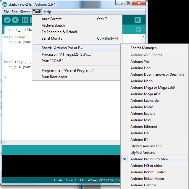
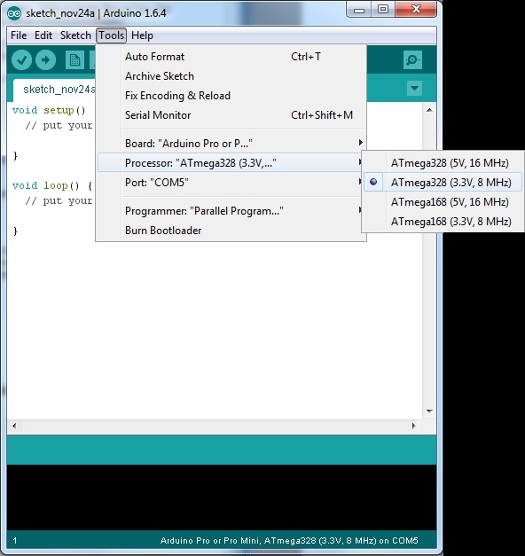
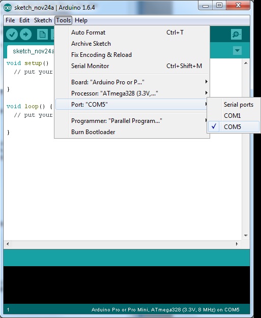
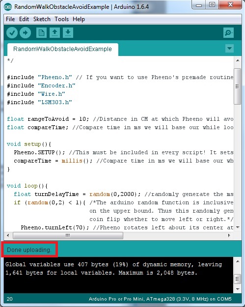
Figure 1: Steps to upload an Arduino script to Pheeno.
Next, go to the Tools tab of the Arduino software and change the processor to the ATMega328 (3.3V, 8MHz) as seen in Figure 1(b).
Finally, go to the Tools tab of the Arduino software and change the port to the one that the robot is plugged into. Typically there should only be one unless you have another USB device that uses serial communication connected. An example can be seen in Figure 1(c). NOTE: The number associated with the port may not be the same!
Now the Arduino software knows what type of board to talk to and through what port. So now you can upload any code you want! To test this all out let’s upload an example script that will be explained later. Go to File –> Examples –> Pheeno –> RandomWalkObstacleAvoidExample. This should load a premade script if you have done everything in “Installing the Pheeno Libraries” section correctly. Now click the arrow in the upper left hand corner of the Arduino software to upload it to the robot. NOTE: THIS SCRI#PT MAKES PHEENO RUN AROUND RANDOMLY! MAKE SURE YOU'RE HOLDING THE PLATFORM SO IT DOESN'T RUN OFF THE TABLE OR MAKE SURE THE ROBOT IS OFF WHILE UPLOADING! When the Arduino software says “Done uploading”, as seen in Figure 1(d), you can disconnect the robot and let it run around.
Pheeno Arduino Library Functions
If you plan on using the Pheeno library for the Arduino, you can take advantage of some premade functions! This section details what they do and what inputs they take briefly! To use the Pheeno library in any Arduino script, you must first include the necessary libraries shown below!
include "Pheeno.h"
Pheeno myRobot = Pheeno(1);
This allows you to use all of the premade functions defined in Pheeno.h and Pheeno.cpp. The Pheeno file that is imported is a premade class. To initialize this class properly you must declare it like is done in the second line of the code above (Pheeno myRobot = Pheeno(1);). Here the class has been named myRobot, but it can be called whatever you would like when creating your own code. From this point onwards it will be assumed this instance of the class will be named myRobot.
myRobot.SETUP()
In the setup section of the Arduino you should include Pheeno.Setup. This function initializes all of the pins on the Arduino correctly and begins certain timers for controllers.
Sensor Reading Functions
myRobot.readIR()
This function takes a reading from all 6 of the IR sensors and converts the measurement to cm. These values are stored in the following variables.
- myRobot.LDistance (The distance received by the Left IR.)
- myRobot.LFDistance (The distance received by the Left Forward IR.)
- myRobot.CDistance (The distance received by the Center IR.)
- myRobot.RFDistance (The distance received by the Right Forward IR.)
- myRobot.RDistance (The distance received by the Right IR.)
- myRobot.BDistance (The distance received by the Back IR.)
readEncoders()
This function returns the current count for the right and left encoder. This subroutine uses the Encoder.h library provided. More information on this library can be found here. These counts are stored in the variables,
- myRobot.encoderCountL (The count of the left encoder.)
- myRobot.encoderCountR (The count of the right encoder.)
Pheeno.readCompass(float magNorthOffset)
This function returns the current heading in degrees from magnetic north in a range of 0° to 359°. The measurement is done with respect to Pheeno’s x-axis as defined in Figure 2. Positive rotation is CCW. The argument given allows the user to input the difference between magnetic north and their desired axis. This allows the function to return the robot’s heading with respect to a given axis. If an argument of 0 is given, the function will return Pheeno’s heading with respect to magnetic north. If an argument of 10 is given, the function will return Pheeno’s heading with respect to an axis 10 degrees CCW of magnetic north. The output is stored in the variable,
- myRobot.IMUOrientation
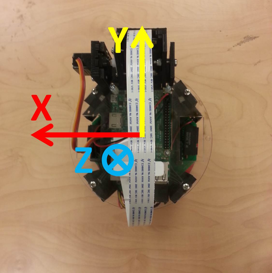
Figure 2: The axis of the IMU on Pheeno.
Pheeno.readAccel()
This function returns the accelerometer readings in the x, y, and z directions. These axis with respect to the robot may be seen in Figure 2. The sensor’s measurements are output in cm/s. The output is stored in the variables,
- myRobot.IMUACCX (The acceleration in the x direction.)
- myRobot.IMUACCY (The acceleration in the y direction.)
- myRobot.IMUACCZ (The acceleration in the z direction.)
Position Update Functions
Pheeno.encoderPositionUpdate(float timeStep)
This is a function that figures out where Pheeno is in space using only the encoder measurements as feedback. The function requires, as input, the time between function calls to calculate how far it has gone in that time. The update is based on the unicycle model (a kinematic model) and will accumulate error over time due to unavoidable wheel slipping and assumption errors from the model.
Pheeno.sensorFusionPositionUpdate(float timeStep, float northOffset)
This is a function that figures out where Pheeno is in space using all of the onboard odometry. The update is based on the unicycle model (a kinematic model). Using a complementary filter, the magnetometer and encoder measurements are used to determine Pheeno’s global orientation and the accelerometer and encoders are used to determine Pheeno’s linear displacement. The encoder measurements are high pass filtered in this function while the accelerometer and compass measurements are low pass filtered. The gains for this filter can be altered in the Pheeno.cpp file. This function requires the time step between function calls (for the encoder estimate updates) and the offset between magnetic north and a desired axis (if the user requires).
Individual Motor Functions
The input of all the following functions, motorSpeed, is a in arduino PWM units which are integers ranging from 0-255. 0 means no motion while 255 is as fast as it can go. These are all open loop. It is advised to put controllers over these. One is provided below!
- myRobot.forwardL(int motorSpeed): Rotates the left motor forward.
- myRobot.forwardR(int motorSpeed): Rotates the right motor forward.
- myRobot.reverseL(int motorSpeed): Rotates the left motor backwards.
- myRobot.reverseR(int motorSpeed): Rotates the right motor backward
Dual Motor Functions
The input of all the following functions, motorSpeed, is a in arduino PWM units which are integers ranging from 0-255. 0 means no motion while 255 is as fast as it can go. These are all open loop. Due to individual differences in the motors, construction of the robot, or the environment there could be errors in the desired motion (i.e. forward will not drive perfectly straight).
- myRobot.forward(int motorSpeed): Rotates both motors forwards at the same speed.
- myRobot.reverse(int motorSpeed): Rotates both motors backwards at the same speed.
- myRobot.turnRight(int motorSpeed): Rotates both motors in opposite directions at the same speed such that Pheeno rotates to its right (clockwise).
- myRobot.turnLeft(int motorSpeed): Rotates both motors in opposite directions at the same speed such that Pheeno rotates to its left (counter clockwise).
Stopping Functions
- Pheeno.noMotion(): Stops the motion of both motors but still allows passive rotation.
- Pheeno.brake(): Brakes both motors which does not allow passive rotation (this can be overcome with enough torque).
Controller Functions
PIDMotorControl(float desLVel, float desRVel)
This is a standard PID controller that maintains the speed of the left and right motors. The inputs are the desired right and left wheel angular velocities in rad/s. The controller has been designed around a 0.05 second time step. The gains of the system can be changed in the Pheeno.cpp file if so desired.
PIDWayPointControl(float u1, float u2, float desVelocity, float timeStep)
This is a standard PID controller moves Pheeno from its current location to a new desired location. The PID controller maintains Pheeno’s heading in the correct direction while driving at a desired velocity. The inputs are the desired global X-Position (cm), desired global Y-Position (cm), desired linear velocity (cm/s), and the time step (ms) of the controller. The controller has been designed around a 0.1 second time step. The gains of the system can be changed in the Pheeno.cpp file.
rotateAboutICC(float R, float WSpeed)
This function drives Pheeno in a circle of a given radius at a desired angular speed. The inputs of the function are R the radius of the desired circle (cm), WSpeed (rad/s) the desired angular speed the circle is traversed. The function uses the PIDMotorControl function described in PIDMotorControl section.
Calibrating Pheeno’s IMU
Manual Calibration
For manual calibration open the script ManualValuesIMU.ino in the Arduino folder in the GitHub repository for Pheeno. To understand the calibration routine used in the following scripts, this is an Arduino script that will print out the accelerometer and magnetometer values. This script should be used if the EEPROM can no longer store information, to understand how the calibration is done, or to get the magnetic north offset used in other scripts.
Once uploading the script do not unplug the USB cord from the computer. Turn on the robot and open the serial monitor in the Arduino software. There should be numbers scrolling across the screen like in Figure 3. The first set of numbers under the “Magnetometer!” line are two vectors of the min and max readings of the magnetometer along the {x, y, z} axis. The second set of numbers under “Accelerometer!” are the averaged accelerometer measurements along the x, y, z axis. The last set of numbers under “Orientation!” is the current direction the robot has measured facing with respect to magnetic north (in degrees!).
To use this script, place the robot where the experiment will take place without disconnecting it from the computer. Turn on the robot, open the serial monitor, and let it sit still for a period of time. During this time the accelerometer values are being averaged. These values will be non zero due to the natural slant of the ground or the orientation of the IMU mounted in the Pheeno robot. After a good amount of time has passed (~30 seconds), record the accelerometer values. These will be the biases you subtract off your readings to get an unbiased reading during your experiments. Next pick up Pheeno and rotate the robot about its three axis. Do this several times. When you place it back on the ground you should notice the vectors under the Magnetometer have changed. Record these values. These are the max and min values of the magnetic field in your experimental space and allow for Pheeno to better predict its heading with respect to magnetic north. The orientation in this script is just to give an idea on how well the compass is calibrated with default values. Spin Pheeno 90 degrees and see if the angle does change by about 90 degrees.
Now that you have recorded the values open ManualInputEEPROM.ino. This script writes the values you have recorded to the EEPROM of the Arduino. The EEPROM of the Arduino is like a mini hard drive where you can save data that won’t be erased when the power to the robot is lost (very useful for calibration data!). Insert the data you have written down in the correct spots of the code (described below).
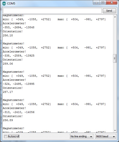
Figure 3: The serial output of the CalibrateIMU script.
This paragraph briefly describes the ManualVluesIMU.ino code shown below. Lines 2 and 3 import the correct libraries used to get data from the LSM303D IMU onboard the robot. Lines 6 and 7 set up the LSM303 library for the rest of the script creating two vectors to store the max and min values for the magnetometer. Lines 9 to 11 contain variables that store the acceleration mean values. Line 13 creates a counter to help with the acceleration means. The setup first starts the serial port with a bit rate of 9600. Then sets up the two libraries that were imported. Line 25 increments the count variable. Line 26 gets new updated data from the LSM303D. Lines 30 to 36 update the min and max values of the magnetometer vector. Lines 40 to 42 update the mean of the acceleration variables. Lines 45 to 59 simply format and perform the prints that occurs through the serial.
/*
This script is used to calibrate the Pheeno robot's IMU. Instructions for use can be found in the Pheeno Robot Programming Guide.
*/

include "Wire.h"
include "LSM303.h"

LSM303 compass;
LSM303::vector<int16_t> running_min = {32767, 32767, 32767};
LSM303::vector<int16_t> running_max = {-32768, -32768, -32768};

float accX = 0;
float accY = 0;
float accZ = 0;

float count = 0;

char report[80];

void setup() {
    Serial.begin(9600);
    Wire.begin();
    compass.init();
    compass.enableDefault();
}

void loop() {
    count = count + 1;
    compass.read();

    // Compass Max and Min
    running_min.x = min(running_min.x, compass.m.x);
    running_min.y = min(running_min.y, compass.m.y);
    running_min.z = min(running_min.z, compass.m.z);

    running_max.x = max(running_max.x, compass.m.x);
    running_max.y = max(running_max.y, compass.m.y);
    running_max.z = max(running_max.z, compass.m.z);

    // Acceleration Mean
    accX = (count - 1)/count * accX + 1/count * compass.a.x;
    accY = (count - 1)/count * accY + 1/count * compass.a.y;
    accZ = (count - 1)/count * accZ + 1/count * compass.a.z;


    snprintf(report, sizeof(report), "min: %+6d, %+6d, %+6d    max: %+6d, %+6d, %+6d",
    running_min.x, running_min.y, running_min.z,
    running_max.x, running_max.y, running_max.z);

    Serial.println("Magnetometer!");
    Serial.println(report);
    Serial.println("Accelerometer!");
    Serial.print(int(accX));
    Serial.print(", ");
    Serial.print(int(accY));
    Serial.print(", ");
    Serial.println(int(accZ));
    Serial.println("Orientation!");
    Serial.println(360-compass.heading());
    Serial.println();
}
This paragraph briefly describes the ManualValuesIMU.ino code shown below. Lines 3 and 4 import the libraries used for storing the calibration data. Line 8 should have the values in the {} changed to the ones recorded in ManualValuesIMU.ino. These are your max and min magnetometer readings that are used to determine the robot’s orientation. Lines 11 to 13 should have their values changed to the accelerometer values recorded earlier. All the values entered above should be integers! The rest of the code simply stores all of these values into the EEPROM.
/*
This script is used to calibrate the Pheeno robot's IMU. Stores the values in the EEPROM.
*/

include "LSM303.h"
include "EEPROM.h"

LSM303 compass;
// Input Compass Values Here!
LSM303::vector<int16_t> running_min = {32767, 32767, 32767}, running_max = {-32768, -32768, -32768};

// Input Accelerometer Values Here!
int accX = 0;
int accY = 0;
int accZ = 0;

int eeAddress = 0;

void setup() {
    // Store Values to the EEPROM
    EEPROM.put(eeAddress, int(accX));
    eeAddress += sizeof(int);
    EEPROM.put(eeAddress, int(accY));
    eeAddress += sizeof(int);
    EEPROM.put(eeAddress, int(accZ));
    eeAddress += sizeof(int);

    // Store Values to the EEPROM
    EEPROM.put(eeAddress, running_min.x);
    eeAddress += sizeof(int);
    EEPROM.put(eeAddress, running_min.y);
    eeAddress += sizeof(int);
    EEPROM.put(eeAddress, running_min.z);
    eeAddress += sizeof(int);

    // Store Values to the EEPROM
    EEPROM.put(eeAddress, running_max.x);
    eeAddress += sizeof(int);
    EEPROM.put(eeAddress, running_max.y);
    eeAddress += sizeof(int);
    EEPROM.put(eeAddress, running_max.z);
    eeAddress += sizeof(int);
}

void loop() {
}
EEPROM Automatic Calibration
To calibrate Pheeno automatically, open the script AutomaticCalibrateIMU.ino in the Arduino folder in the GitHub repository for Pheeno. This script does essentially what the manual script described above does(“Manual Calibration” section). To use this calibration program, upload the script then place Pheeno in the arena you wish to run the experiment in. Turn on the robot, it should sit still for about a minute then rotate for another minute. Once it has stopped moving it should be calibrated!
/*
This script is used to calibrate the Pheeno robot's IMU. Stores the values in the EEPROM.
*/

include <Wire.h>
include <LSM303.h>
include <EEPROM.h>

LSM303 compass;
LSM303::vector<int16_t> running_min = {32767, 32767, 32767}, running_max = {-32768, -32768, -32768};

float accX = 0;
float accY = 0;
float accZ = 0;

float count = 1;
int eeAddress = 0;

///////////////////////////////////////////////////////////
// Pin Numbers Here
///////////////////////////////////////////////////////////

const uint8_t IRC = 0;  // Analog input center sensor
const uint8_t IRLF = 1; // Analog input left forward sensor
const uint8_t IRL = 2;  // Analog input left sensor
const uint8_t IRB = 3;  // Analog input back sensor
const uint8_t IRRF = 6; // Analog input right forward sensor
const uint8_t IRR = 7;  // Analog input right sensor

const uint8_t PWMA = 11; // A Motor PWM Control
const uint8_t PWMB = 5;  // B Motor PWM Control

const uint8_t AMotor1 = 9;  // A Motor Direction 1
const uint8_t AMotor2 = 10; // A Motor Direction 2

const uint8_t BMotor1 = 7; // B Motor Direction 1
const uint8_t BMotor2 = 6; // B Motor Direction 2

const uint8_t STBY = 8; // Standby pin to turn off motors.

const uint8_t interruptL = 3;
const uint8_t interruptR = 2;

const uint8_t noInterruptL = 12;
const uint8_t noInterruptR = 13;

void setup() {
    Wire.begin();
    compass.init();
    compass.enableDefault();
}

void loop() {

    for(int i = 0; i<1000; i++){
        compass.read();

        // Acceleration Mean
        accX = (count - 1)/count * accX + 1/count * compass.a.x;
        accY = (count - 1)/count * accY + 1/count * compass.a.y;
        accZ = (count - 1)/count * accZ + 1/count * compass.a.z;

        count = count + 1;
    }

    // Store Values to the EEPROM
    EEPROM.put(eeAddress, int(accX));
    eeAddress += sizeof(int);
    EEPROM.put(eeAddress, int(accY));
    eeAddress += sizeof(int);
    EEPROM.put(eeAddress, int(accZ));
    eeAddress += sizeof(int);

    turnRight(100);
    for(int j = 0; j<5000; j++){
        compass.read();

        // Compass Max and Min
        running_min.x = min(running_min.x, compass.m.x);
        running_min.y = min(running_min.y, compass.m.y);
        running_min.z = min(running_min.z, compass.m.z);

        running_max.x = max(running_max.x, compass.m.x);
        running_max.y = max(running_max.y, compass.m.y);
        running_max.z = max(running_max.z, compass.m.z);
    }

    // Store Values to the EEPROM
    EEPROM.put(eeAddress, running_min.x);
    eeAddress += sizeof(int);
    EEPROM.put(eeAddress, running_min.y);
    eeAddress += sizeof(int);
    EEPROM.put(eeAddress, running_min.z);
    eeAddress += sizeof(int);

    // Store Values to the EEPROM
    EEPROM.put(eeAddress, running_max.x);
    eeAddress += sizeof(int);
    EEPROM.put(eeAddress, running_max.y);
    eeAddress += sizeof(int);
    EEPROM.put(eeAddress, running_max.z);
    eeAddress += sizeof(int);

    while (true){
        noMotion();
    }
}

void noMotion(){
    // Turns the motors off. (They can still rotate passively)
    digitalWrite(STBY, LOW); // Motors OFF
}

void forwardL(int motorSpeed){
    // Left motor drive forward.
    if (motorSpeed>255) {
        motorSpeed=255;
    }
    if (motorSpeed<0) {
        motorSpeed=0;
    }
    digitalWrite(STBY, HIGH); // Motors ON
    analogWrite(PWMA, motorSpeed); // Speed
    digitalWrite(AMotor1, LOW);
    digitalWrite(AMotor2, HIGH);
}

void reverseR(int motorSpeed){
    // Right motor drive backwards.
    if (motorSpeed>255) {
        motorSpeed=255;
    }
    if (motorSpeed<0) {
        motorSpeed=0;
    }
    digitalWrite(STBY, HIGH); // Motors ON
    analogWrite(PWMB, motorSpeed); // Speed
    digitalWrite(BMotor1, HIGH);
    digitalWrite(BMotor2, LOW);
}

void turnRight(int motorSpeed){
    reverseR(motorSpeed);
    forwardL(motorSpeed);
}
Checking the EEPROM Calibration
If you want to make sure the calibration information was stored correctly, open the EEPROMReadCalibrateData.ino script. Upload it to Pheeno and keep the robot connected to the computer. You do not need to turn on the robot as the computer can power the Arduino. If you open the serial monitor in the Arduino software, you should see a printout like the one seen in Figure 4. The numbers should be integers (definitely) and non-zero (most likely). If not something in the calibration has gone wrong.
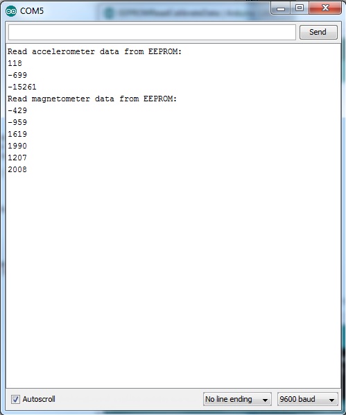
Figure 4: The serial output of the EEPROMReadCalibrateData.ino script.
Pheeno Arduino Examples
This section describes the specific Arduino examples below. To open any of the examples below, open the Arduino software then navigate to File –> Examples –> Pheeno –> EXAMPLE.
OpenLoopMotionExample.ino
This code is meant as an intro to making Pheeno move around using open loop motor functions. Here open loop just means there is no check to make sure the wheels are doing what you want them to. When this script is uploaded to Pheeno and it is turned on it should drive forward, turn right, turn left, then drive backwards and stop. It should (in theory) start and stop at the same location. However, in reality this will not be the case the longer it runs.
Lines 4 and 5 are just the normal includes that are needed when using the Pheeno library. The setup uses the standard Pheeno library setup to initialize pins correctly and start timers. Inside the loop are where all the functions occur. To drive the robot forward, line 13 uses Pheeno.forward(150). This causes both wheels on the robot to spin forward. The 150 argument can be thought of as a speed. The argument in these parenthesis is an Arduino PWM integer ranging from 0-255 where 0 is stopped and 255 is the fastest the robot can go. Once this argument is given, the wheels will continue to spin this way until a different command is given. The delay(5000) on line 14 keeps any other functions from being called for 5000 ms (5 seconds). This means the robot will drive forward for 5 seconds. NOTE: BE VERY CAREFUL WHEN USING DELAYS IN OTHER CODE, THEY STOP EVERYTHING IN THE SCRIPT MEANING NO SENSORS CAN BE READ AND CONTROLLERS WILL NOT BE UPDATED!. The rest of the script follows a similar pattern to cause the robot to turn right and left, then back up and stop. Since this is in a loop, this will keep repeating until you turn the robot off or upload a different code.
/*
This script gives an introduction to making Pheeno drive open loop. There is no feedback, motors move at the given input but can be prone to errors in manufacturing and environment. Everything will be done with delays, however, it should be noted you cannot use delays  if you require sensor feedback.
*/

// If you want to use Pheeno's premade routines import this!
#include "Pheeno.h"
// The argument is the type of robot (0 = Original DD, 1 = Tank Treads,
// 2 = Tripod DD)
Pheeno myRobot = Pheeno(0);


void setup(){
    // This must be included in every script! It sets up all the pins on the robot!
  myRobot.SETUP();
}

void loop(){
  myRobot.forward(150);   // Pheeno drives forward.
  delay(5000);              // Wait for 5 seconds
  myRobot.turnRight(70);  // Pheeno turns right.
  delay(2000);              // Wait for 2 seconds.
  myRobot.turnLeft(70);   // Pheeno rotates left.
  delay(2000);              // Wait for 2 seconds.
  myRobot.reverse(150);   // Pheeno drives backwards.
  delay(5000);              // Wait for 5 seconds
  myRobot.brake();        // Brake the motors.
  delay(3000);              // Wait for 3 seconds.
}
PIDMotorControlExample
Now if you want some feedback when using the motors, this script uses a function that actually checks if the motors are moving at the speed you have given to them. Lines 4 and 6 import the libraries needed to use the Pheeno library. Line 8 sets the desired velocity you want the robot to move at. This is in cm/s and can be changed to move the robot slower or faster. Line 12 converts the linear velocity to a rotational one that the controller acts on. The setup uses the standard setup and the loop uses the PIDMotorControl function described in the “PIDMotorControl” section.
/*
This script gives an introduction to using encoder feedback on Pheeno's motors. In this code we will make Pheeno drive straight at a given velocity. A premade PID controller has been made to control the individual motor speeds and can be accessed using the Pheeno.PIDMotorControl() function. The PID feedback relies solely on the encoders so wheel slip can cause to robot to diverge from a straight line path! The gains of the PID can be adjusted in the Pheeno.cpp file.
*/

// If you want to use Pheeno's premade routines import this!
#include "Pheeno.h"

// The argument is the type of robot (0 = Original DD, 1 = Tank Treads,
// 2 = Tripod DD)
Pheeno myRobot = Pheeno(0);

// The linear velocity we want the robot to go in cm/s
float desVel = 10;

void setup(){
  // This must be included in every script! It sets up all the pins on the
  // robot!
  myRobot.SETUP();
  // Converts the linear velocity to rotational velocity for the controller.
  desVel = desVel * 2/myRobot.wheelDiameter;
}

void loop() {
  myRobot.PIDMotorControl(desVel, desVel);
}
RandomWalkExample
The random walk example simply makes the robot move around in a random walk.
/*
This script gives an introduction to making Pheeno drive a random walk. It uses delays and Arduino PWM units (int, 0-255) for speed.
*/

// If you want to use Pheeno's premade routines import these libraries!!
#include "Pheeno.h"

// The argument is the type of robot (0 = Original DD, 1 = Tank Treads,
// 2 = Tripod DD)
Pheeno myRobot = Pheeno(0);

void setup() {
    // This must be included in every script! It sets up all the pins on the
    // robot!
    myRobot.SETUP();
}

void loop(){
    // Randomly generate the ms of delay for the turn.
    float turnDelayTime = random(0,2000);
    if (random(0,2) < 1){
        // The arduino random function is inclusive on the lower bound and
        // exclusive on the upper bound. Thus this randomly generates 0 and 1
        // and creates a coin flip whether to move left or right.

        // Pheeno rotates left about its center at a given speed
        // (range 0 to 255).
        myRobot.turnLeft(150);
        // Wait a random amount of time defined above.
        delay(turnDelayTime);
    } else {
        // Pheeno rotates right about its center at a given speed
        // (range 0 to 255).
        myRobot.turnRight(150);
        // Wait a random amount of time defined above.
        delay(turnDelayTime);
    }

    // ms of delay for the run (you can make this random if you desire!).
    float runDelayTime = 1000;
    // Pheeno moves forward at a given speed (range 0 to 255).
    myRobot.forward(120);
    // Wait a random amount of time defined above.
    delay(runDelayTime);
}
SerialPrintSensors
This reads all the sensors on the robot and prints them out through the serial port. To use this, upload this script to the robot, turn on the robot, then, while the robot is still attached to the computer, open the serial monitor. The sensor values should be output.
/*
This script constantly reads Pheeno's onboard sensors and prints their results through the serial port.
*/

// If you want to use Pheeno's premade routines import this!
#include "Pheeno.h"

// The argument is the type of robot (0 = Original DD, 1 = Tank Treads,
// 2 = Tripod DD)
Pheeno myRobot = Pheeno(0);

// A delay time to make manually reading the serial port easier!
float delayTime = 500;

void setup(){
    // Starts the serial port, with the argument being the bit rate.
    Serial.begin(9600);
    // This must be included in every script! It sets up all the pins on the
    // robot!
    myRobot.SETUP();
    Serial.println("A test read of all Pheeno's sensors!");
}

void loop() {
    // Reads all of the IR sensor distances in cm.
    myRobot.readIR();
    // Reads how many total ticks have occured on the encoders.
    myRobot.readEncoders();
    // Reads the compass. The argument is the offset between your global x-axis
    // and magnetic north.
    myRobot.readCompass(0);
    // Reads the accelerometer.
    myRobot.readAccel();

    Serial.println("IR Sensor Distances!");
    Serial.println("[Left IR, Left Forward IR, Center IR, Right Forward IR, Right IR, Back IR]");
    Serial.print("[");
    Serial.print(myRobot.LDistance);
    Serial.print(", ");
    Serial.print(myRobot.LFDistance);
    Serial.print(", ");
    Serial.print(myRobot.CDistance);
    Serial.print(", ");
    Serial.print(myRobot.RFDistance);
    Serial.print(", ");
    Serial.print(myRobot.RDistance);
    Serial.print(", ");
    Serial.print(myRobot.BDistance);
    Serial.println("]");
    Serial.println("Encoder Counts!");
    Serial.println("[Left Encoder, Right Encoder]");
    Serial.print("[");
    Serial.print(myRobot.encoderCountL);
    Serial.print(", ");
    Serial.print(myRobot.encoderCountR);
    Serial.println("]");
    Serial.println("IMU Measurements (Accelerometer and Magnetometer/Compass)!");
    Serial.println("[X Acceleration, Y Acceleration, Z Acceleration, Heading]");
    Serial.print("[");
    Serial.print(myRobot.IMUACCX);
    Serial.print(", ");
    Serial.print(myRobot.IMUACCY);
    Serial.print(", ");
    Serial.print(myRobot.IMUACCZ);
    Serial.print(", ");
    Serial.print(myRobot.IMUOrientation);
    Serial.println("]");
    Serial.println();
    Serial.println();

    // A simple delay to make manual reading of the serail port easier.
    delay(delayTime);
}
DriveCircleExample
This example causes Pheeno to drive in a circle of radius R such that it traverses the circle at w rad/s.
/*
This script gives an introduction to making Pheeno turn with encoder feedback. This uses the same PID controller as PIDMotorControlExample. In this example Pheeno will drive in a circle of radius R at angular speed w.
*/

// If you want to use Pheeno's premade routines import this!
#include "Pheeno.h"

Pheeno myRobot = Pheeno(0);

//The angular velocity Pheeno will traverse the circle (rad/s)! CCW direction
// is positive velocity!
float desW = 3.14;
// The radius of the circle Pheeno will be on (cm).
float R = 10;

void setup(){
    // This must be included in every script! It sets up all the pins on the
    // robot!
    myRobot.SETUP();
}

void loop(){
    // The inputs to this function are: (Desired Radius (cm), Desired Angular
    // Velocity (rad/s)).
    myRobot.rotateAboutICC(R, desW);
}
RandomWalkObstacleAvoidExample
This function does the same random walk as done in the RandomWalkExample section but does not use delays so it can read the IR range sensors to avoid obstacles during the walk.
/*
This script gives an introduction to making Pheeno drive a random walk. While doing the random walk, it will avoid obstacles.
*/

// If you want to use Pheeno's premade routines import these libraries!!
#include "Pheeno.h"

// The argument is the type of robot (0 = Original DD, 1 = Tank Treads,
// 2 = Tripod DD)
Pheeno myRobot = Pheeno(0);

// Distance in CM at which Pheeno will avoid obstacles.
float rangeToAvoid = 10;
// Compare time in ms we will base our while loops off of. Initialized in the
// set up!
float compareTime;

void setup(){
    // This must be included in every script! It sets up all the pins on the
    // robot!
    myRobot.SETUP();
    // Compare time in ms we will base our while loops off of.
    compareTime = millis();
}

void loop(){
    // Randomly generate the ms of delay for the turn.
    float turnDelayTime = random(0,2000);
    if (random(0,2) < 1){
        // The arduino random function is inclusive on the lower bound and
        // exclusive on the upper bound. Thus this randomly generates 0 and 1
        // and creates a coin flip whether to move left or right.

        // Pheeno rotates left about its center at a given speed
        // (range 0 to 255).
        myRobot.turnLeft(150);
        // Wait a random amount of time defined above.
        while(millis() - compareTime < turnDelayTime){
            avoidObstacles();
        }
        compareTime=millis();
    } else {
        // Pheeno rotates right about its center at a given speed
        // (range 0 to 255).
        myRobot.turnRight(150);
        // Wait a random amount of time defined above.
        while(millis() - compareTime < turnDelayTime){
            avoidObstacles();
        }
        compareTime=millis();
    }

    // ms of delay for the run (you can make this random if you desire!).
    float runDelayTime = 1000;
    // Pheeno moves forward at a given speed (range 0 to 255).
    myRobot.forward(120);
    // Wait a random amount of time defined above.
    while(millis() - compareTime < runDelayTime){
        avoidObstacles();
    }
    compareTime=millis();
}

void avoidObstacles(){
    myRobot.readIR();
    // Speed at which to rotate away from collisions (In arduino PWM units
    // (int, 0 to 255)).
    int collisionRotateSpeed = 150;
    if (myRobot.CDistance < rangeToAvoid){
        if(abs((myRobot.RDistance - myRobot.LDistance) < 5 || (myRobot.RDistance > rangeToAvoid && myRobot.LDistance > rangeToAvoid)) ) {
            if(random(0,2) < 1) {
                myRobot.turnLeft(collisionRotateSpeed);
            } else {
                myRobot.turnRight(collisionRotateSpeed);
            }
        }
        if (myRobot.RDistance < myRobot.LDistance) {
            myRobot.turnLeft(collisionRotateSpeed);
        } else {
            myRobot.turnRight(collisionRotateSpeed);
        }
    } else if (myRobot.RFDistance < rangeToAvoid && myRobot.LFDistance < rangeToAvoid) {
        if(random(0,2) < 1){
            myRobot.turnLeft(collisionRotateSpeed);
        } else {
            myRobot.turnRight(collisionRotateSpeed);
        }
    } else if (myRobot.RFDistance < rangeToAvoid) {
        myRobot.turnLeft(collisionRotateSpeed);
    } else if (myRobot.LFDistance < rangeToAvoid) {
        myRobot.turnRight(collisionRotateSpeed);
    } else if (myRobot.LDistance < rangeToAvoid) {
        myRobot.turnRight(collisionRotateSpeed);
    } else if (myRobot.RDistance < rangeToAvoid) {
        myRobot.turnLeft(collisionRotateSpeed);
    }
}
WayPointEncoders
This script makes Pheeno drive a square of side 75 cm. It uses encoder feedback to determine its global position. If you wish Pheeno to drive to different way points simply change the array in lines 13 and 14.
/*
This script makes Pheeno drive to different way points using only encoder feedback!
*/

// If you want to use Pheeno's premade routines import this!
#include "Pheeno.h"

// The argument is the type of robot (0 = Original DD, 1 = Tank Treads,
// 2 = Tripod DD)
Pheeno myRobot = Pheeno(0);

// Time step for the odometry update to operate at (10Hz)!
float timeStep = 100;
// Iterator through the way points.
int count = 0;
// Desired linear velocity of Pheeno in cm/s.
float desVel = 10;

// --- WayPoint Path Points ---
// Pheeno's array of waypoint x positions.
float botYf[4]={0,0,75.0000,75.00};
// Pheeno's array of waypoint y positions.
float botXf[4]={0,75.0000,75.0000,0};

//Number of waypoints entered.
int numWayPoints = (sizeof(botXf)/sizeof(float));

void setup(){
    //This must be included in every script! It sets up all the pins on the
    // robot!
    myRobot.SETUP();
}

void loop() {
    while (calculateDistance(myRobot.botXPos,myRobot.botYPos, botXf[count%numWayPoints], botYf[count%numWayPoints]) > 3){
        myRobot.PIDWayPointControl(botXf[count%numWayPoints],botYf[count%numWayPoints],desVel,timeStep);
        // Encoders used for state estimates.
        myRobot.encoderPositionUpdate(timeStep);
    }
    count ++;
}

float calculateDistance(float x1, float y1, float x2, float y2){
    //Calculates the distance the robot is from the desired way point
    float space = sqrt(sq((x1 - x2)) + sq((y1 - y2)));
    return space;
}
wayPointSensorFusion
This also makes Pheeno drive in a square of side 75 cm but uses a complementary filter for sensor fusion for updating the robots global position. The robot should be calibrated before this script is run!
/*
This script makes Pheeno drive to different way points using a complementary filter on the magnetometer, accelerometer, and encoders for feedback!
*/


// If you want to use Pheeno's premade routines import this!
#include "Pheeno.h"

// The argument is the type of robot (0 = Original DD, 1 = Tank Treads,
// 2 = Tripod DD)
Pheeno myRobot = Pheeno(0);

// Time step for the odometry update to operate at (10Hz)!
float timeStep = 100;
// Iterator through the way points.
int count = 0;
// Desired linear velocity of Pheeno in cm/s.
float desVel = 15;
// Difference between magnetic north and the global X axis
float northOffset = 12.9;

// --- WayPoint Path Points ---
// Pheeno's array of waypoint x positions.
float botYf[4]={0,0,75.0000,75.00};
// Pheeno's array of waypoint y positions.
float botXf[4]={0,75.0000,75.0000,0};

// Number of waypoints entered.
int numWayPoints = (sizeof(botXf)/sizeof(float));

void setup(){
    // This must be included in every script! It sets up all the pins on the
    // robot!
    myRobot.SETUP();
}

void loop() {
    while (calculateDistance(myRobot.botXPos,myRobot.botYPos,botXf[count%numWayPoints],botYf[count%numWayPoints]) > 3){
        myRobot.PIDWayPointControl(botXf[count%numWayPoints],botYf[count%numWayPoints],desVel,timeStep);
        // Encoders used for state estimates.
        myRobot.sensorFusionPositionUpdate(timeStep, northOffset);
    }
    count ++;
}

float calculateDistance(float x1, float y1, float x2, float y2){
    // Calculates the distance the robot is from the leader
    float space = sqrt(sq((x1 - x2)) + sq((y1 - y2)));
    return space;
}