Introduction
The “Pheeno” is a modular robot developed by the Autonomous Collectives Lab at Arizona State University in the spring of 2015 for usage in bio-inspired engineering collectives. The goal of the ACS lab is to develop control frameworks for multi-robot systems; however, Pheeno is a small, versatile robot that can be used in any number of settings, whether individually or in groups. This robot itself is a two-wheeled, cylindrical device controlled by an Arduino Pro Mini and Raspberry Pi with the opportunity to develop modules to be added on to the robot. A completed Pheeno robot can be seen in Figure 1.1.
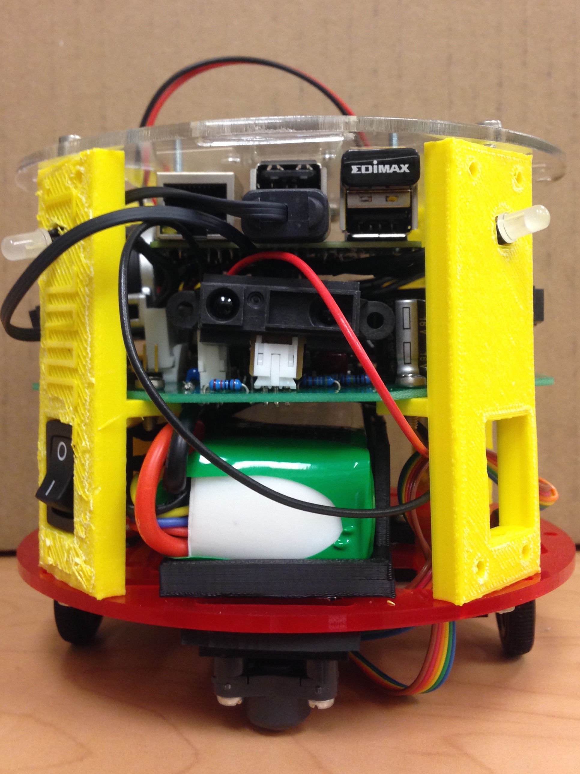
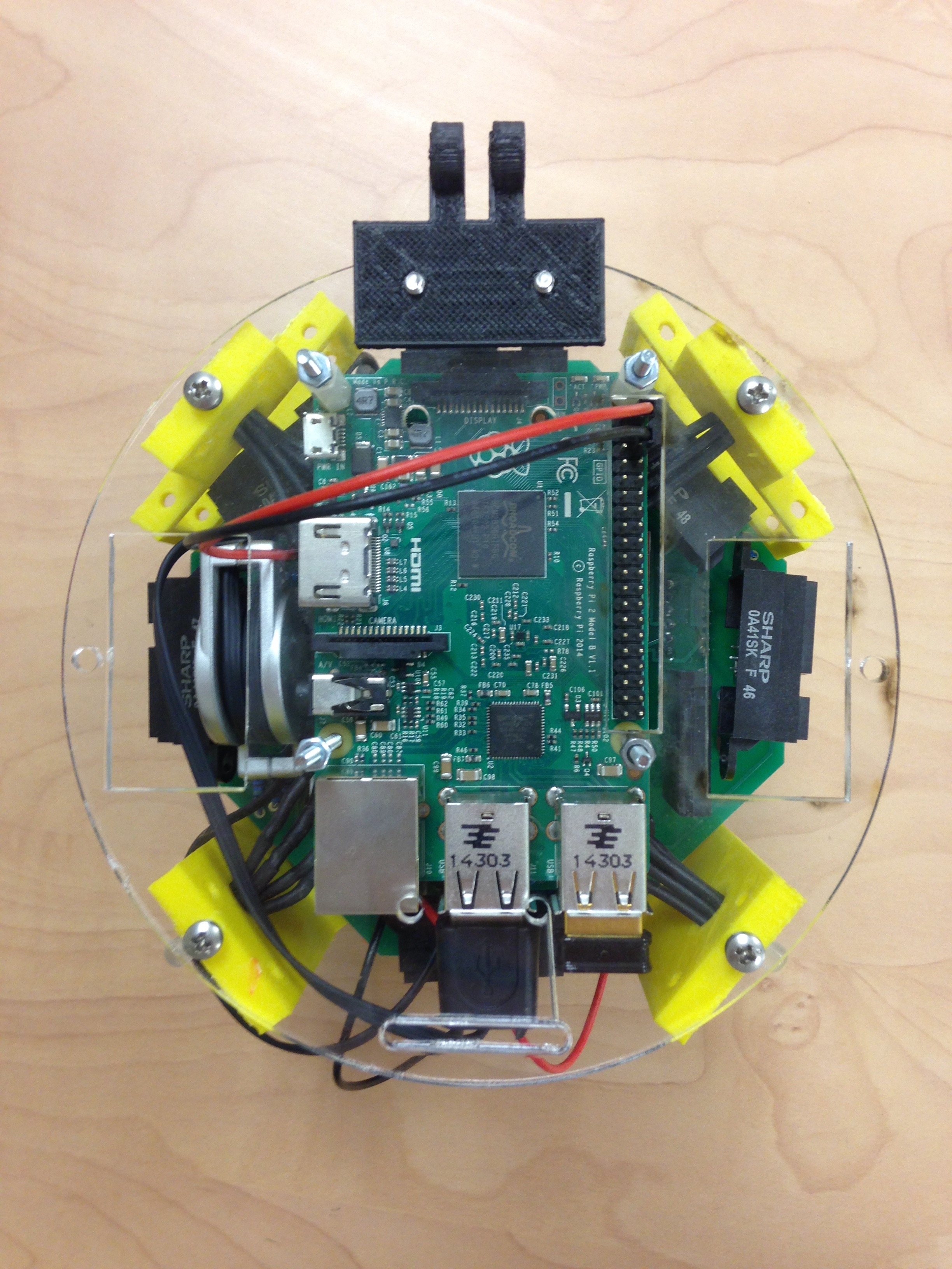
Figure 1.1: Completed Pheeno.
This guide will give step by step directions for constructing the Pheeno along with detailed photos and descriptions of the parts necessary. We at the ACS lab are glad you have chosen to take the time to build this robot, and we wish you the best of luck.
PCB Assembly
The first and possibly most difficult stage of the Pheeno construction is the assembly and soldering of parts onto the custom-designed printed circuit board (PCB). The A diagram of the PCB is shown in Figure 2.2; consult it carefully in conjunction with the pictures and descriptions below (an electronic schematic can be provided upon request). The population of the board takes approximately two hours, and the final result is Figure 2.1.
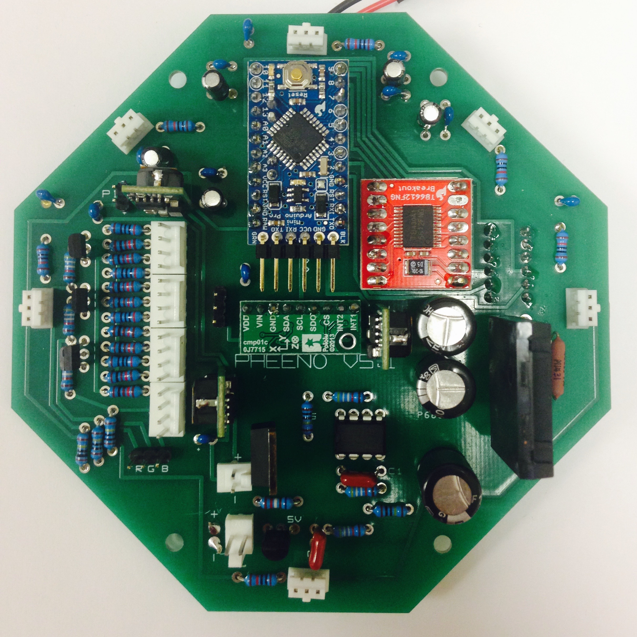
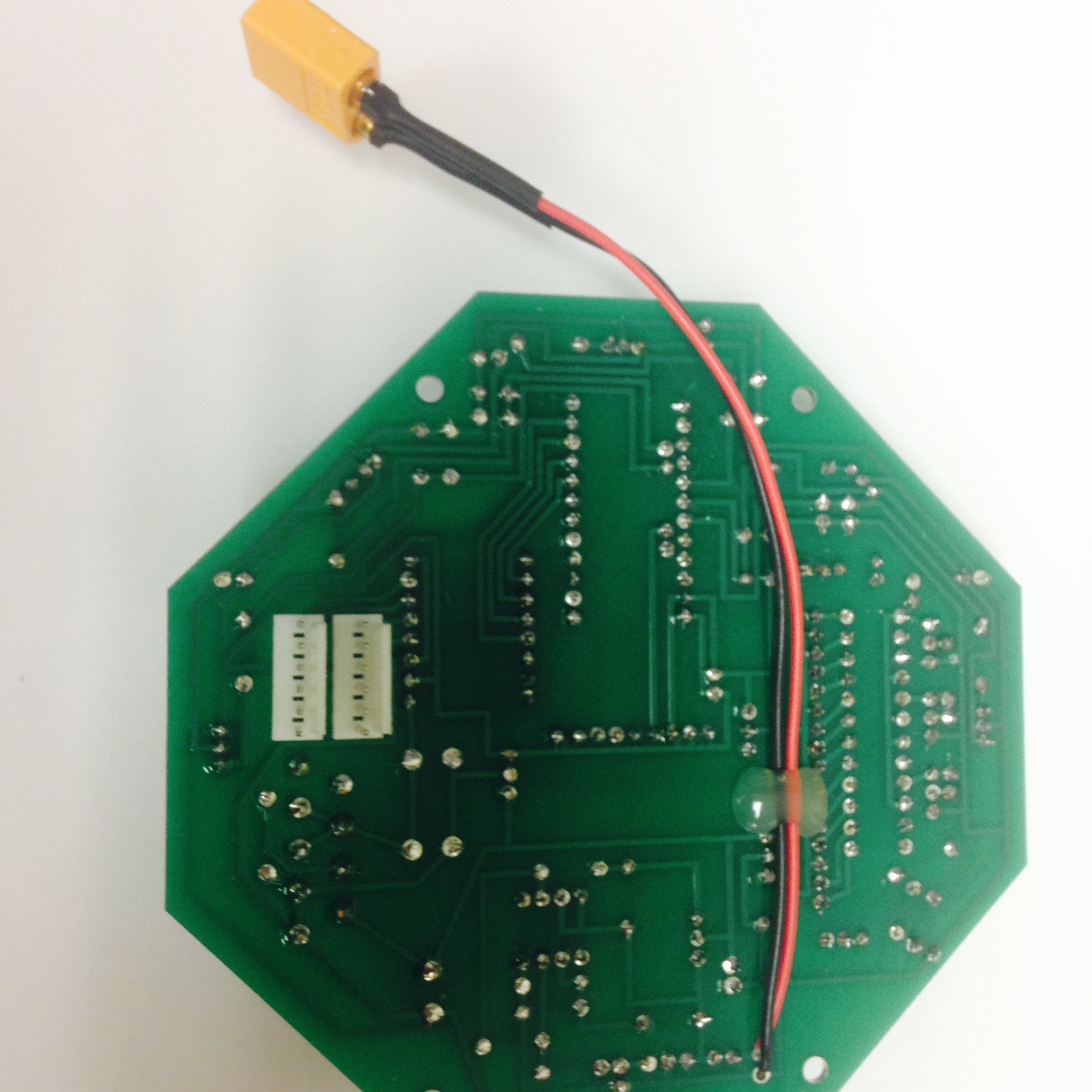
Figure 2.1: Completed Printed Circuit Board.
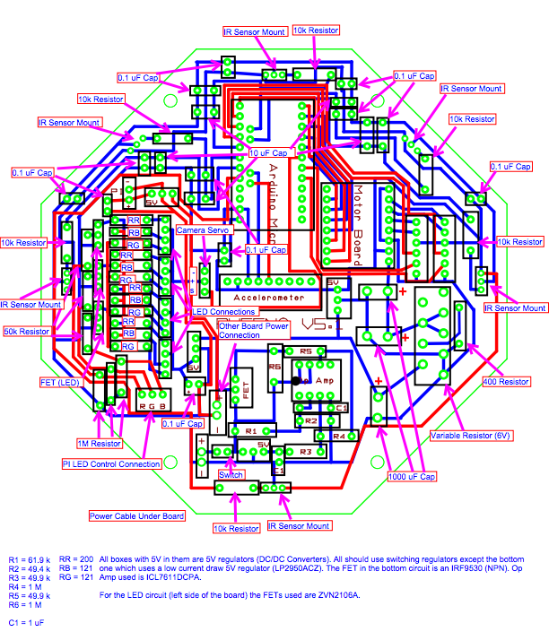
Figure 2.2: Wiring diagram for the PCB of Pheeno.
IR Mounts
The mounts for the IR sensors must first be constructed. The components can be seen in Figure 2.3(a) Pull out three pins from a row of male breakaway pins, crimp them into Molex 22-30 gauge crimp contacts, and insert each pin into a 3-pin female header.
Start with empty PCB board. Insert six mounts, which will hold the IR sensors, along the outside of the board with the pertruding tabs facing outwards, as shown in Figure 2.3(b). It is crucial that the mounts face the correct direction, otherwise the IR sensors will not point outwards. Flip the board over and carefully solder the pins. Clip off the excess length. Note: The thicker pins tend to prevent the heated rosin from flowing effectively, occasionally causing the solder to bridge two pins. Make sure the pins are not shorted out.
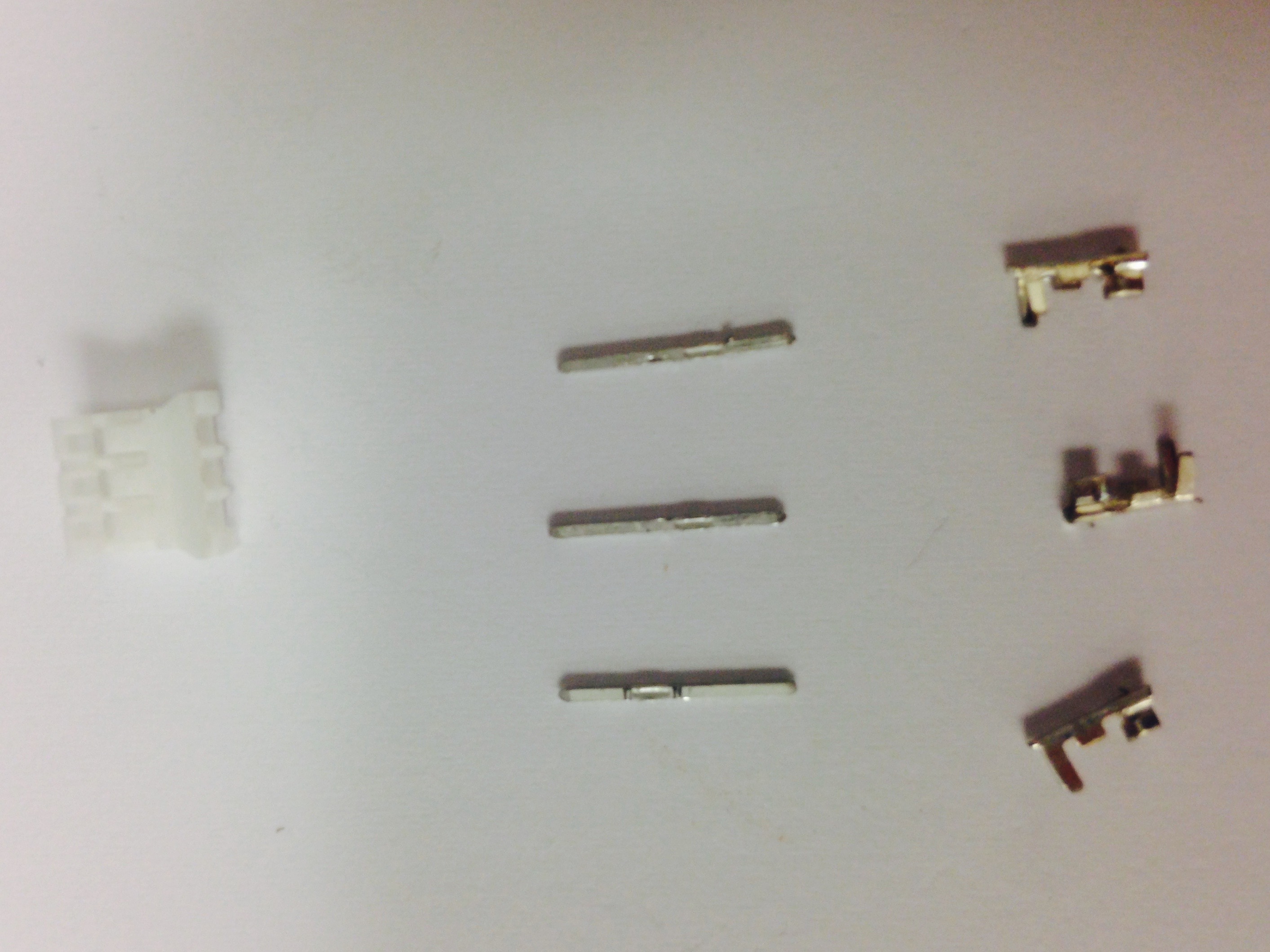
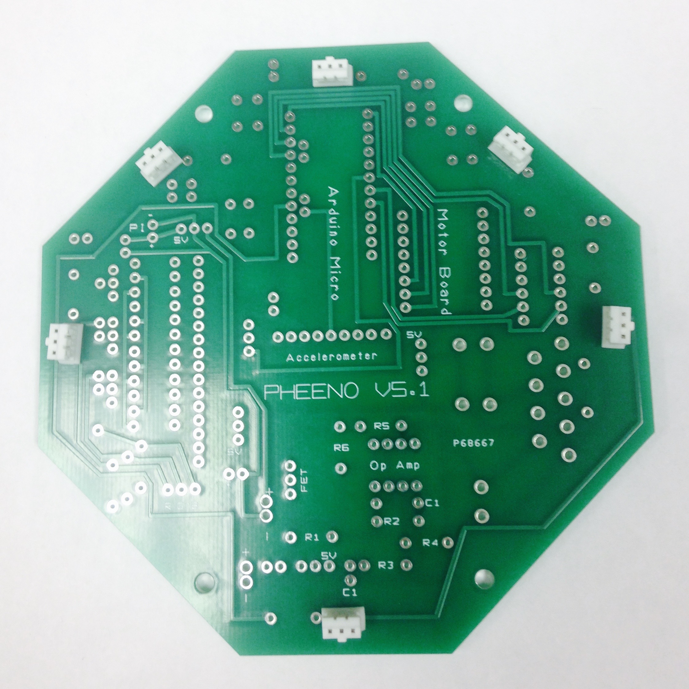
Figure 2.3: IR Mounts.
Resistors
The next step is inserting and soldering the resistors found on the board. Before beginning, it is helpful to gather the necessary types of resistors. The number and size of the resistors needed is shown in Table 2. Bend the leads tightly so that they fit into the holes, and in general follow the wiring diagram from the previous page very carefully. Bend the wires along the back surface of the board to secure each resistor, then solder each hole. Finally, clip the excess wire. Figure 2.4(a) shows the PCB populated with resistors.
| Resistor Resistance | 121 | 10k | 49.9k | 1M | 200 | 61.9 | 400 |
|---|---|---|---|---|---|---|---|
| Number Required | 8 | 6 | 6 | 5 | 4 | 1 | 1 |
Capacitors
Next the capacitors should be soldered to the board. You should always check if the capacitors are electrolytic/tantalum or ceramic/film! Electrolytic/tantalum capacitors have polarity associated with them, meaning a specific lead needs to be grounded. In general capacitors below $1 \si{\micro\farad}$ are ceramic/film and thus can be put in either direction. With the capacitors used in the purchasing sheet provided, the 10 (\si{\micro\farad}) capacitors are electrolytic and the rest are ceramic or film. This means that they must be oriented correctly, with the silver side (negative lead) oriented as seen in Figure 2.4(b). If you are using the schematic the negative lead should be soldered to ground. Insert them in the correct spots and bend the wires back to hold them in place. Make sure the capacitors are pressed as much as possible into the board; this provides less probability of shorts, does not make the board tall, and allows for other components to fit over the capacitors. Figure 2.4(b) displays the population of the PCB with resistors and capacitors.
| Capacitor Capacity | 0.1 | 10 | 1 |
|---|---|---|---|
| Number Required | 11 | 5 | 2 |
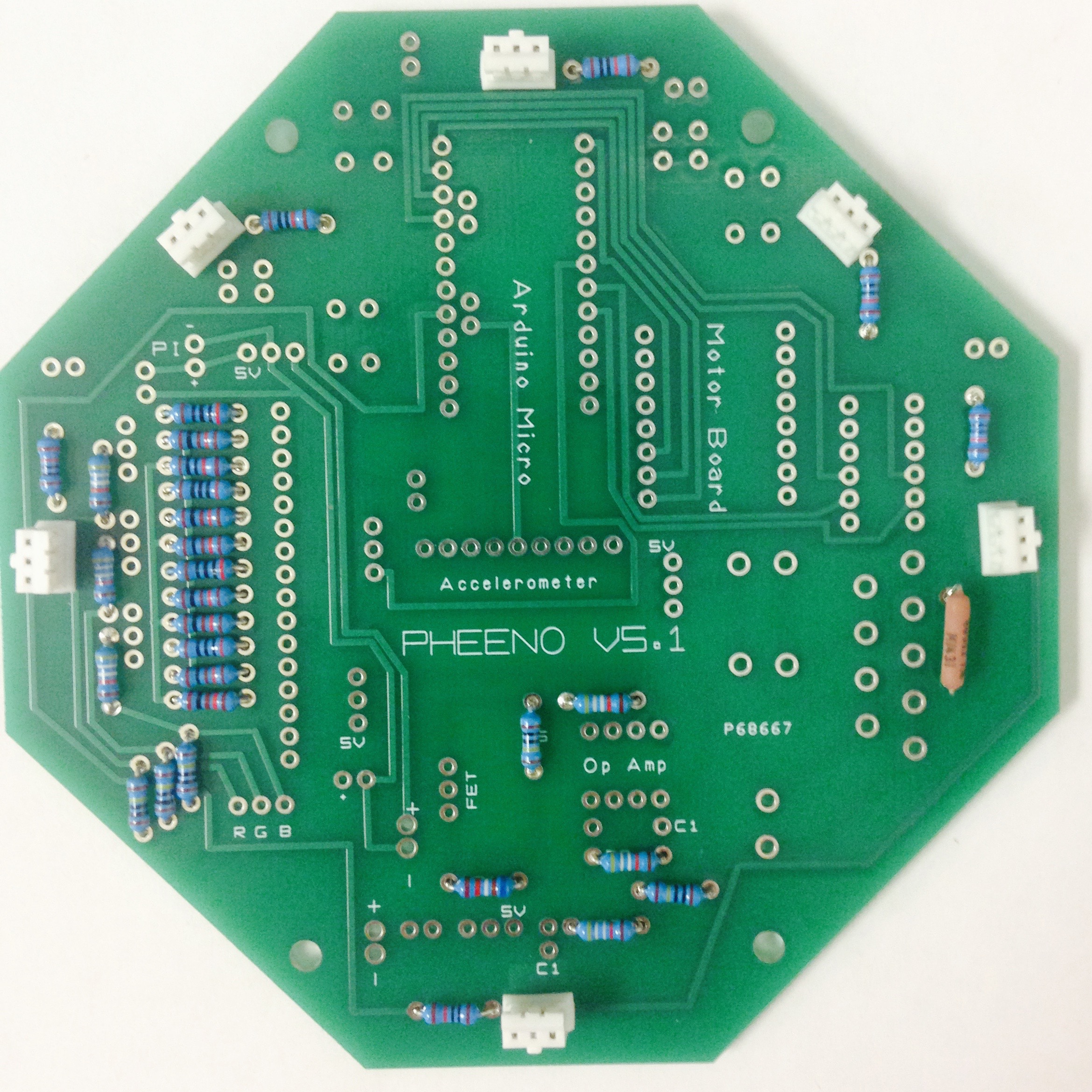
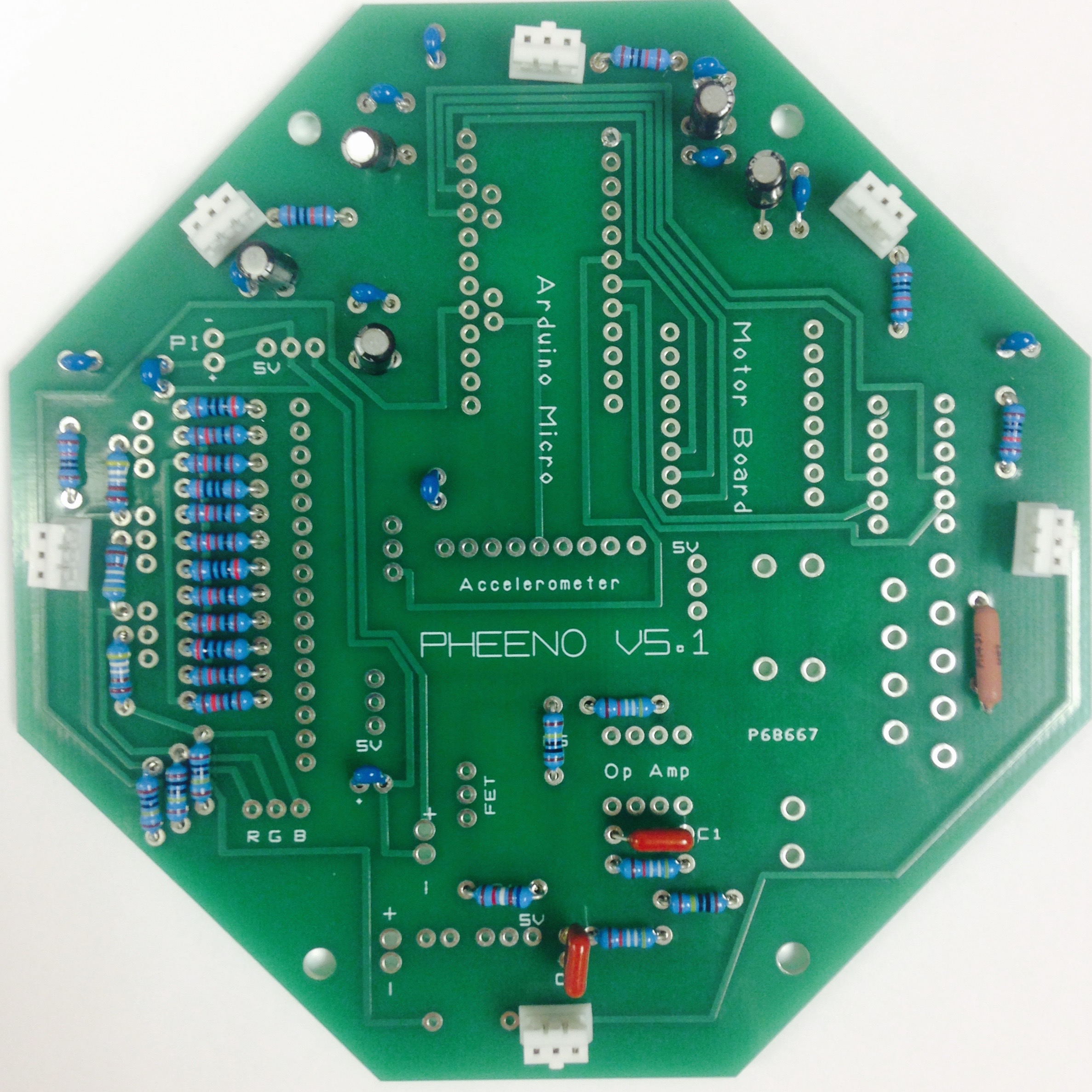
Figure 2.4: PCB with (a) resistors inserted and (b) resistors and capacitors inserted.
Molex Connector Pins, Male Breakaway Pins, and Op-Amp
On the left side of the PCB, to the right of the tightly packed rows of resistors lie 16 holes. Insert into these holes four 4-pin Molex connectors with the tall plastic edge located on the interior side, namely towards the printed words on the board. Each of these connectors will eventually be connected to an LED. Flip the board over and solder the pins securely into each hole. Similarly, two 2-pin Molex connectors can be found at the bottom left of the board. Refer to Figure 2.5 for the correct orientation. One of these connectors runs to the switch for turning the robot on and off. The other connector is an optional set of power pins directly from the Op-Amp circuit that can be used to power attachment boards. Once again flip the board over and solder the white connectors.
Next up, solder several sets of loose breakaway male pins into the board. Insert three connected pins on the lower left-hand side of the board above the “RGB” text; these will eventually connect the LED’s to the Raspberry Pi for control of the lighting. In the middle of the board use another set of three pins. These pins connect to the camera servo. Lastly, solder two pins on the upper left-hand side. Wires from these pins power the Raspberry Pi. A useful tip for soldering these pins is to insert the long edge into a block of foam, that way the pins do not fall out or get oriented incorrectly when the board is flipped for soldering.
A quick component to insert is the Op-Amp. It is the black chip on the lower section of the board depicted in Figure 2.5. Make sure when inserting it the notch is facing the same direction as in the picture!
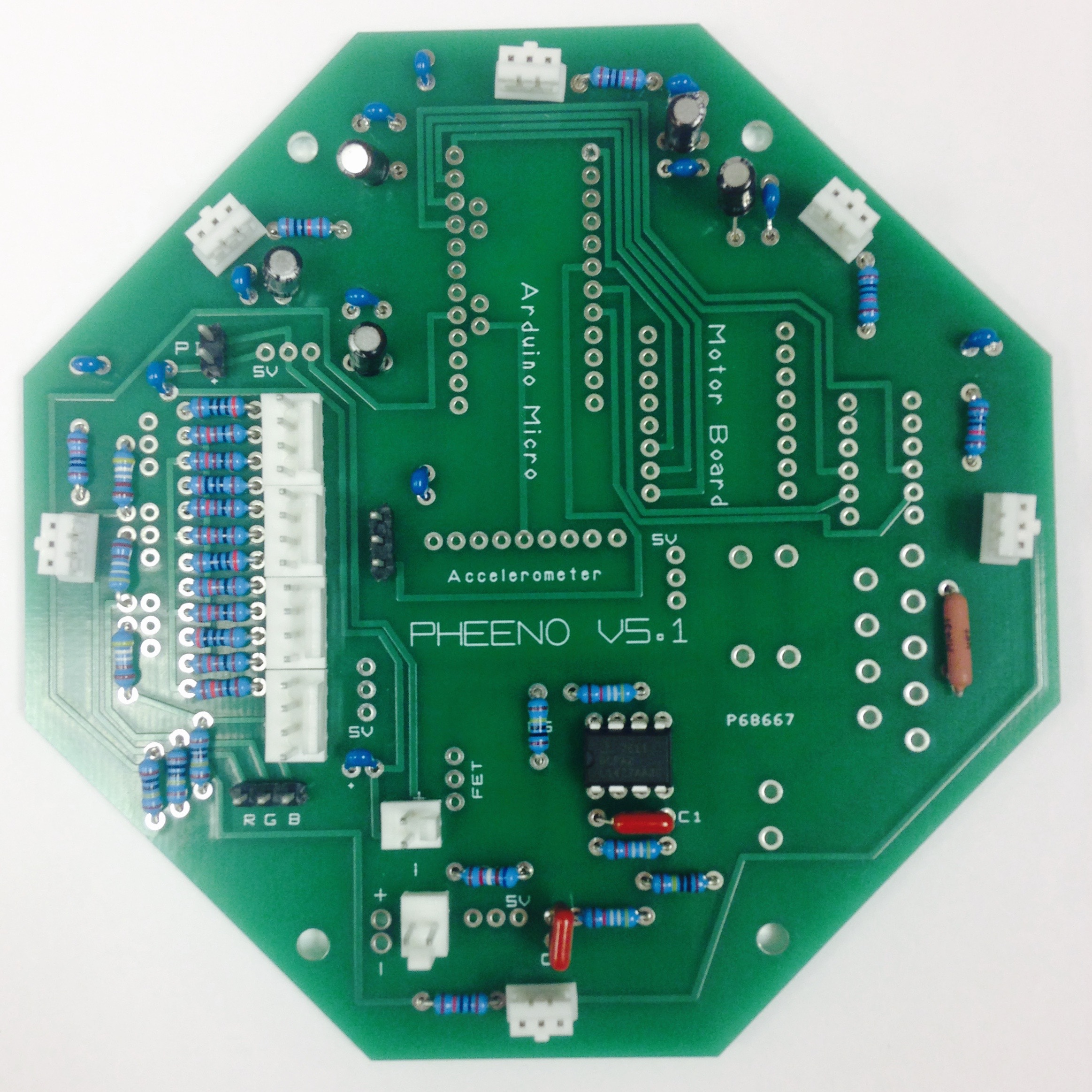
Figure 2.5: Layout of Molex connectors, male headers, and Op-Amp.
Premade Boards
The trickiest part of the PCB may be soldering the attachments of the three boards, the Arduino Pro-Mini, the compass/accelerometer (also referred to as an IMU), and the H-bridge motor controller. The accelerometer is likely the easiest of the three to mount, so start there. Each accelerometer package comes with a set of pins, as can be see in Figure 2.6(a). The male header pins should be soldered such that the text is facing the soldered ends and the hole is in the lower right when looking at the soldered ends. Insert the board into the PCB such that it covers the “Accelerometer” text on the PCB, as seen in Figure 2.7. Balance the accelerometer parallel to the PCB and solder each hole. Clip off the excess length from the pins.
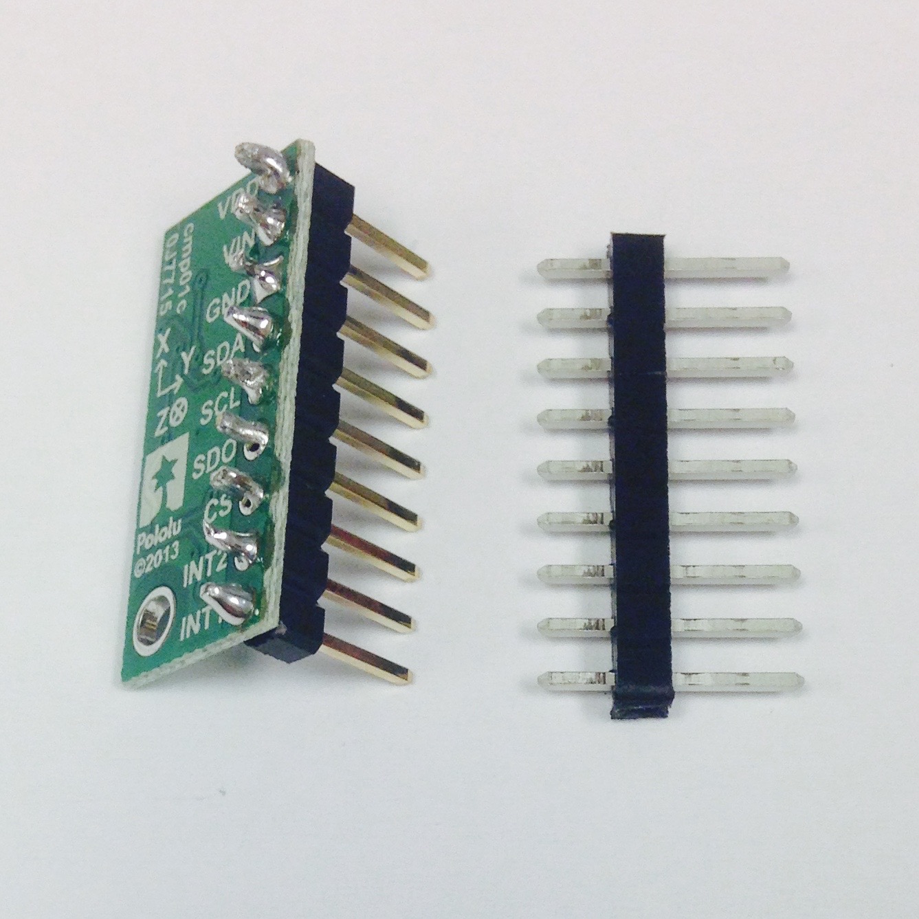
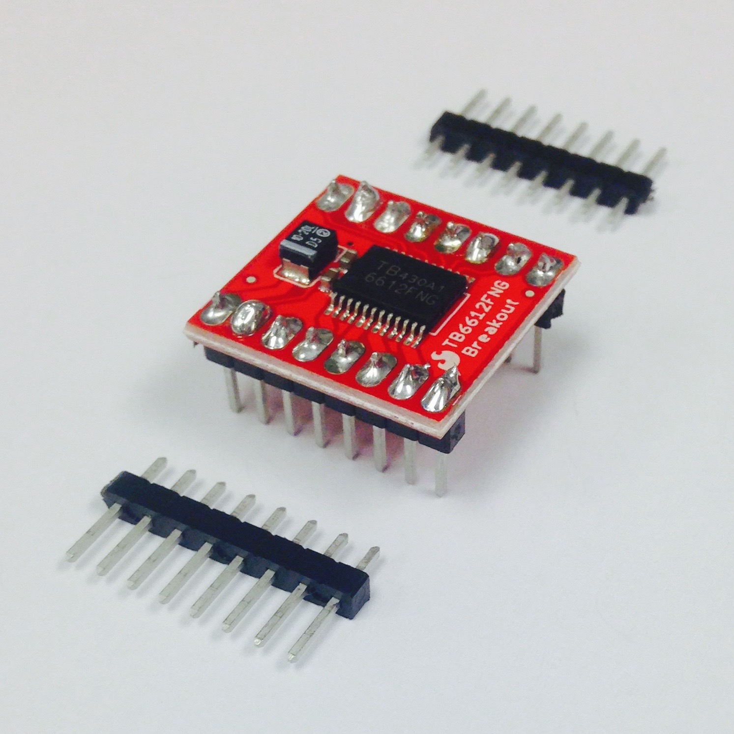
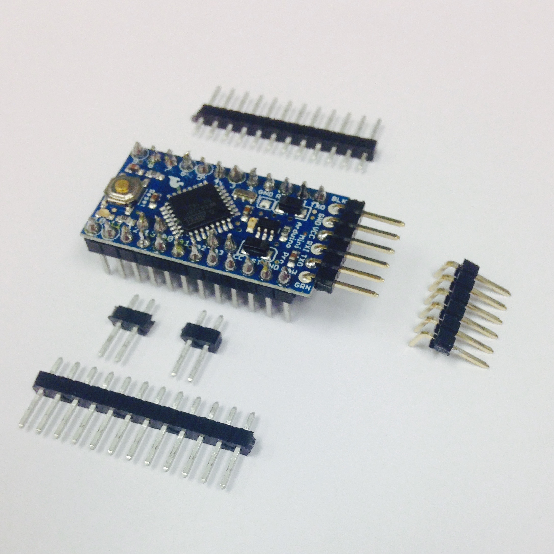
Figure 2.6: (a) Compass/Accelerometer, (b) Motor Board (H-Bridge), (c) Arduino Pro Mini with male header pins soldered to them and free male header pins around the perimeter showing how many were used.
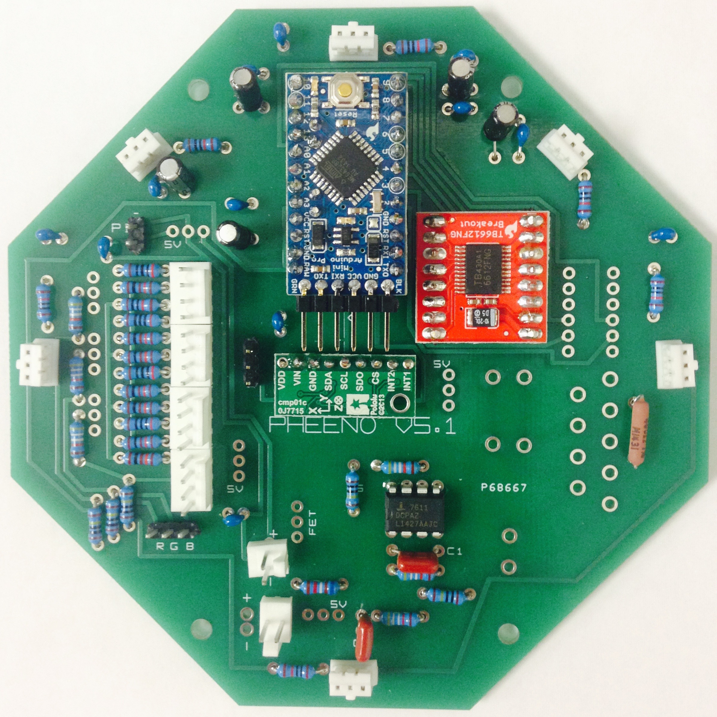
Figure 2.7: Layout of the accelerometer/compass, motor board, and Arduino Pro Mini.
The H-Bridge motor controller is the red board, as seen in Figure 2.6(b). Clip off two sets of 8 male header breakaway pins and insert them into the PCB. The pins should be put through such that the chip on the board is facing the side soldered. Insert the board into the PCB such that the larger chip faces the top the PCB as seen in Figure 2.7. Flip the PCB over and solder the motor board to the PCB.
Last but not least is the Arduino Pro-Mini. Solder two sets of 12 male header pins to the board, along with two sets of 2 pins, as seen in Figure 2.6(c). The pins should be soldered such that the soldered side faces the chip and reset button. In addition, solder 6 right angle male header pins into the holes on the shorter edge of the board. It would seem intuitive to then insert and solder the set-up directly into the PCB; DO NOT DO THIS. Instead insert the same number of female header connectors into the PCB. This extra set of connection allows one to remove the Arduino Pro Mini if necessary and have the right angle headers not interfere with the IMU. Finish connecting and orienting the Arduino as seen in Figure 2.7, with the reset button pointing towards the top of the PCB.
Large/Miscellaneous Components
Up until this point the components inserted into the board have been mostly flat and symmetrical, permitting a balanced surface for soldering the backside of the PCB. However, the remaining components, primarily transistors and voltage regulators (switching DC/DC converters), come in a variety of shapes and sizes. First up are the three 5V switching regulators. Orient these as seen in Figure 2.8(a); they are marked by the “5V boxes” on the wiring diagram. The massive variable regulator (set to 6V) should be inserted on the lower right. It can only fit into the PCB one way. Solder all of these parts carefully so nothing is shorted.
Next up are the three 60 V FET’s (Field Effect Transistors) on the left. Orient the small devices as seen in Figure 2.8(a). A fourth FET, rated at 40V, should be inserted next to the lower 5V regulator. Lastly, three large $1000 \si{\micro\farad}$ capacitors should be soldered in. Similar to the $10 \si{\micro\farad}$ capacitors, the leads must be connected to the correct voltage lines to function (and not pop!). The silver strip points to the left on the upper two and to the bottom on the bottom one.
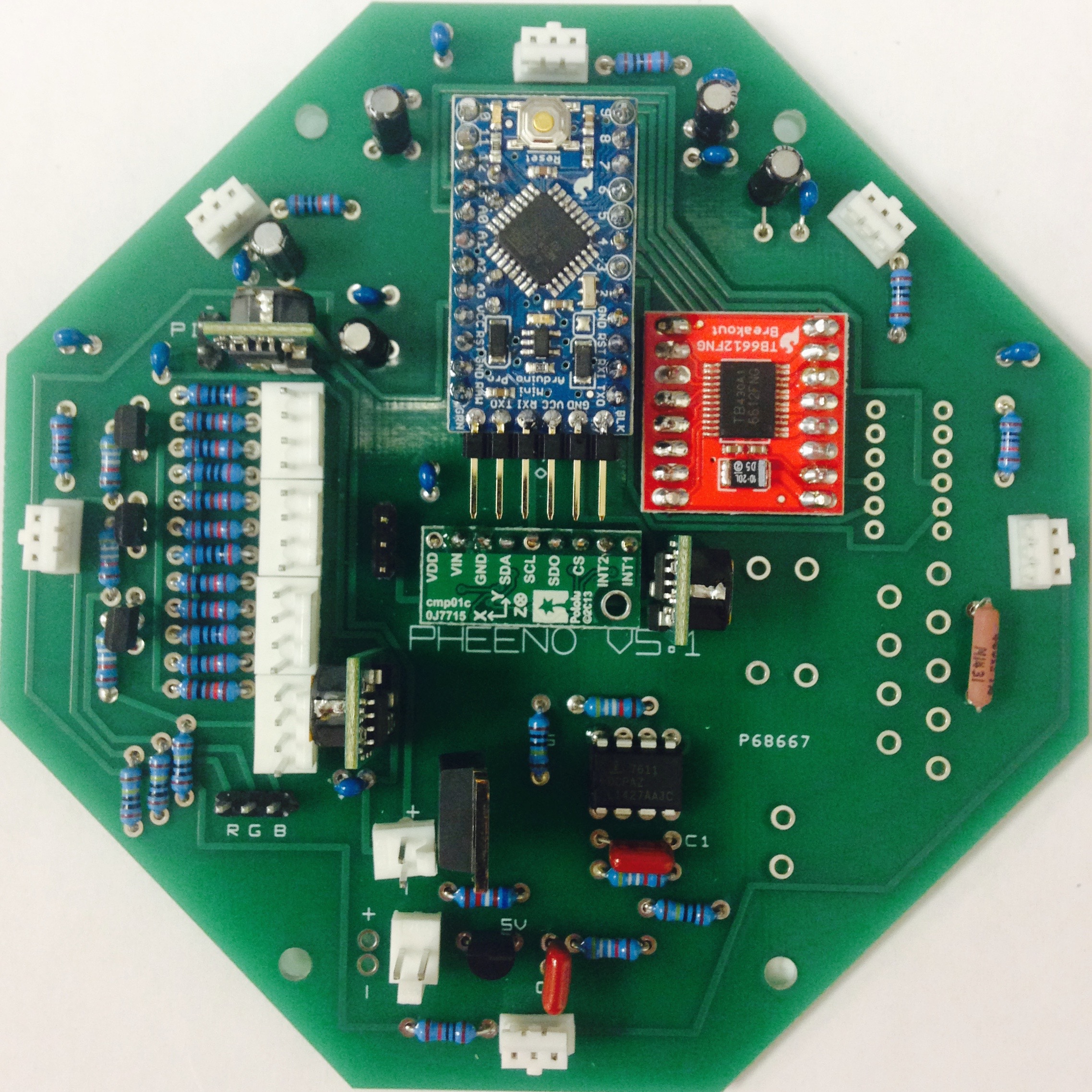
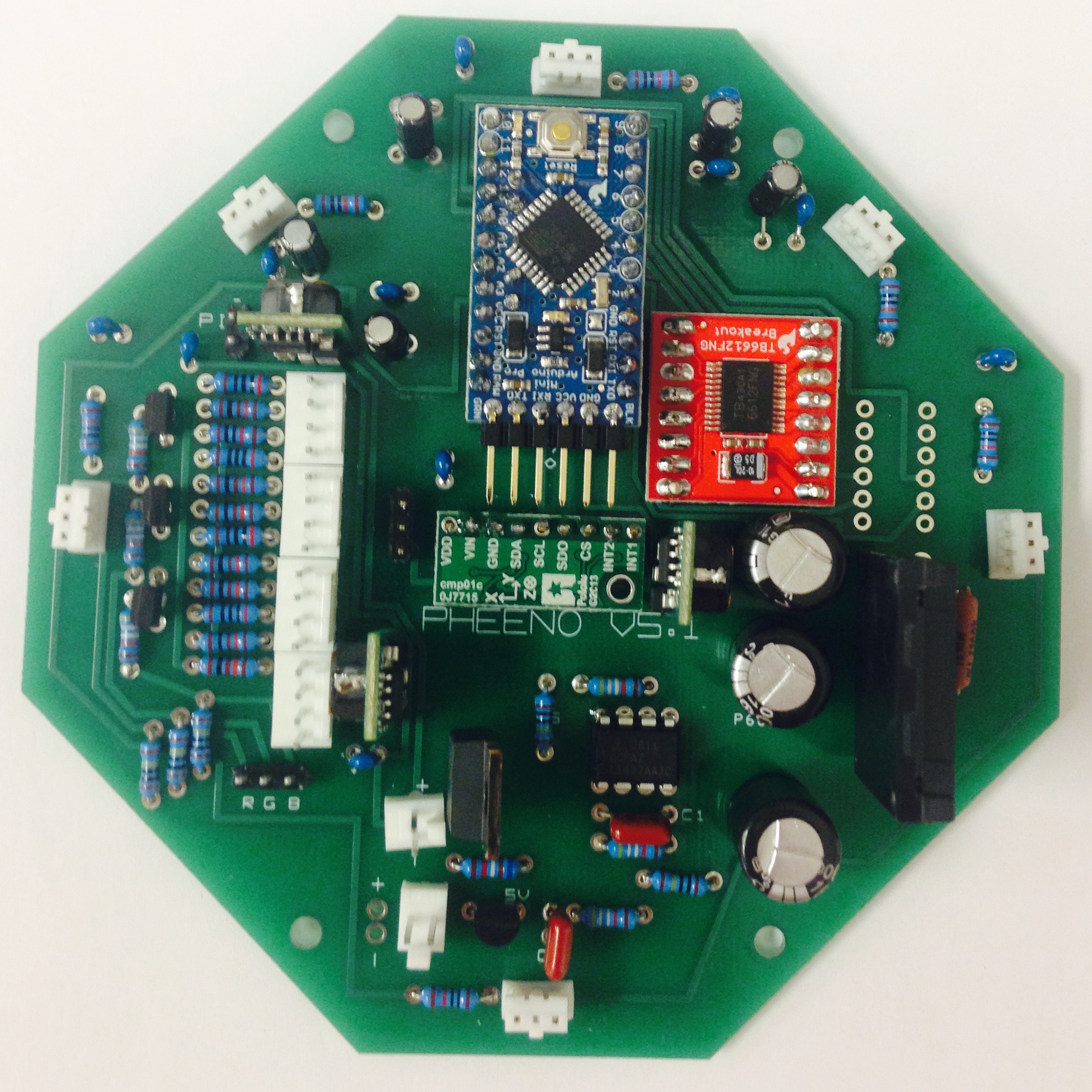
Figure 2.8: Top of the PCB with (a) 5V switching voltage regulators inserted and (b) 5V switching voltage regulators, $1000 \si{\micro\farad}$ capacitors, and variable regulator inserted.
Congratulations, the top side of the board is complete! Check all the components inserted so far and make sure no solder rosin has bridged pins alongside the bottom of the board and no pins are left unsoldered.
Underside of Board
We are close to finishing the PCB. Insert and solder two 6-pin Molex male connectors along the bottom of the board, as seen in Figure 2.9(a). These pins run to the wheel encoders and motor driving lines, so make sure they’re oriented correctly, with the tall white edge towards the center of the board.
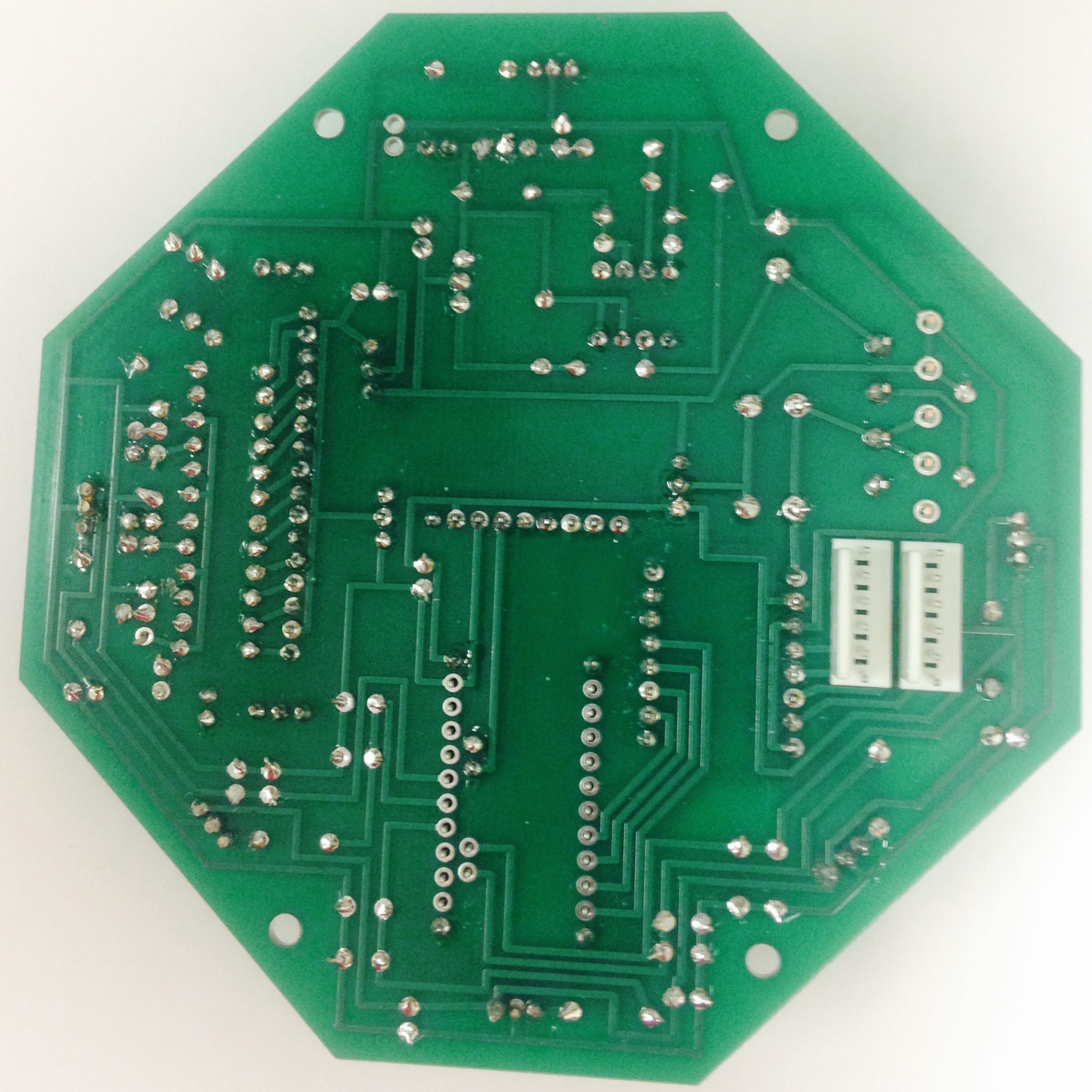
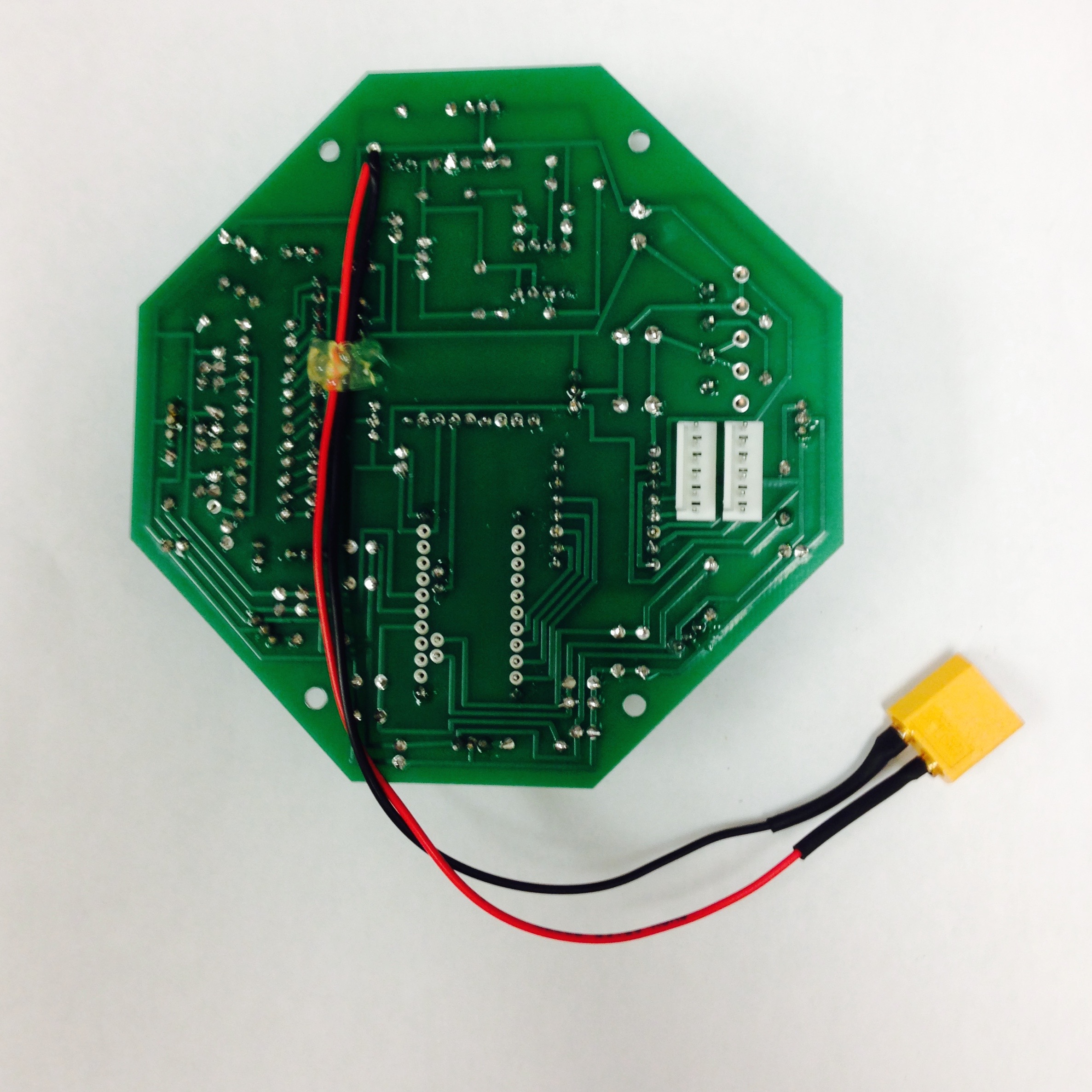
Figure 2.9: Completing the bottom of the PCB with (a) the 6 pin Molex connectors inserted and (b) the power wire inserted.
A power cable must be constructed. Figure 2.10 shows the stages involved in making the jumper cable. First, solder 22 or 20 gague red and black wires to the positive and negative leads of an XT60 male connector. Then, to insulate the leads, use heat shrink wrap to cover the newly soldered leads. Cut the red and black wires to the same length, strip the ends, and insert the wires into the two remaining holes on the PCB (marked $+$ and $-$). Make sure the positive XT60 socket is connected to the $+$ labeled hole and the negative XT60 socket is connected to the $-$ labeled hole. Lay the cable across the back of the board and solder the exposed wire into each hole. To resist wear and possible snapping of the wire at the PCB solder point, we will create a new pivot point for the wire on the board. With the wire pressed against the PCB use hot glue or some other stretchy adhesive to secure the middle of the wire against the board. We use hot glue seen in Figure 2.9(b).
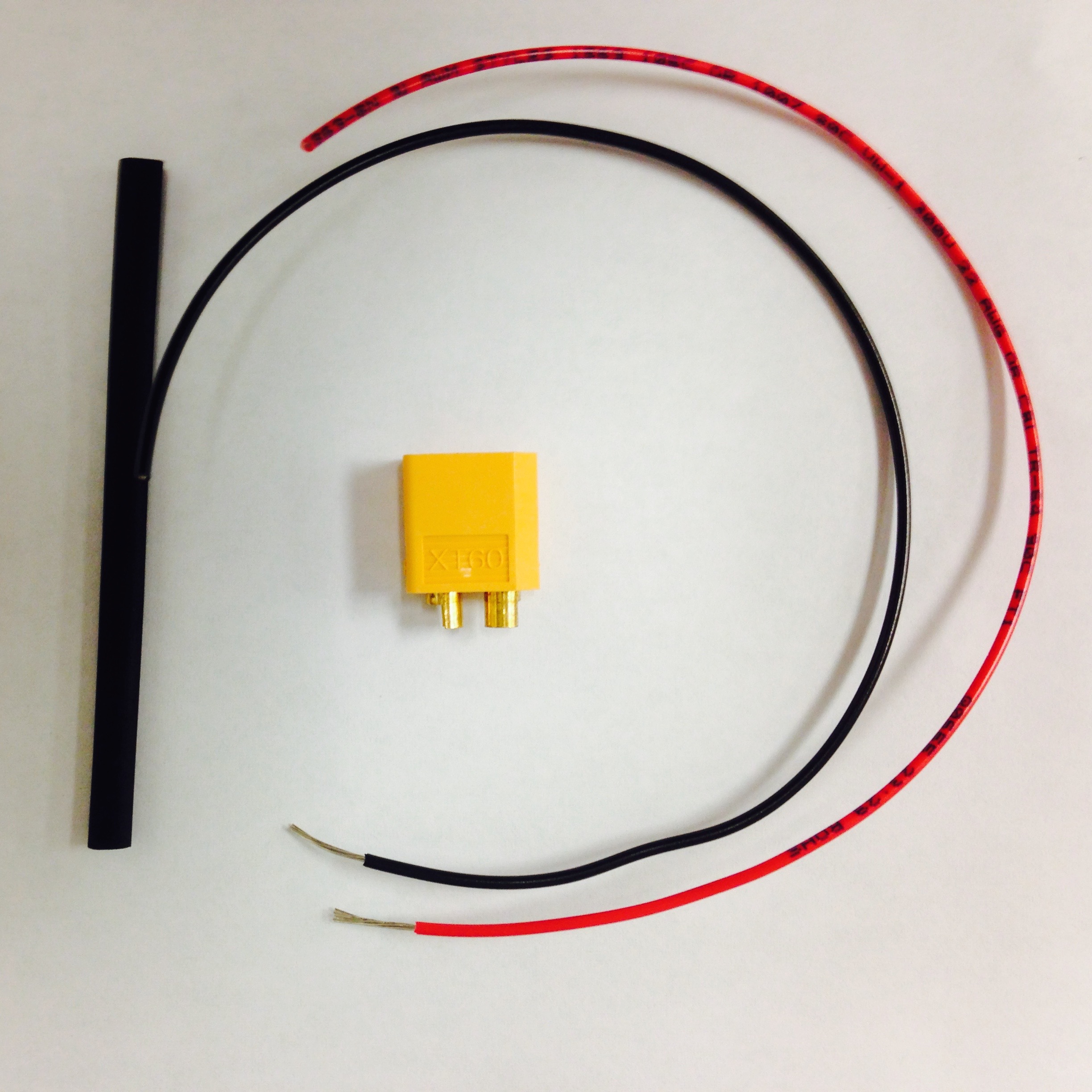
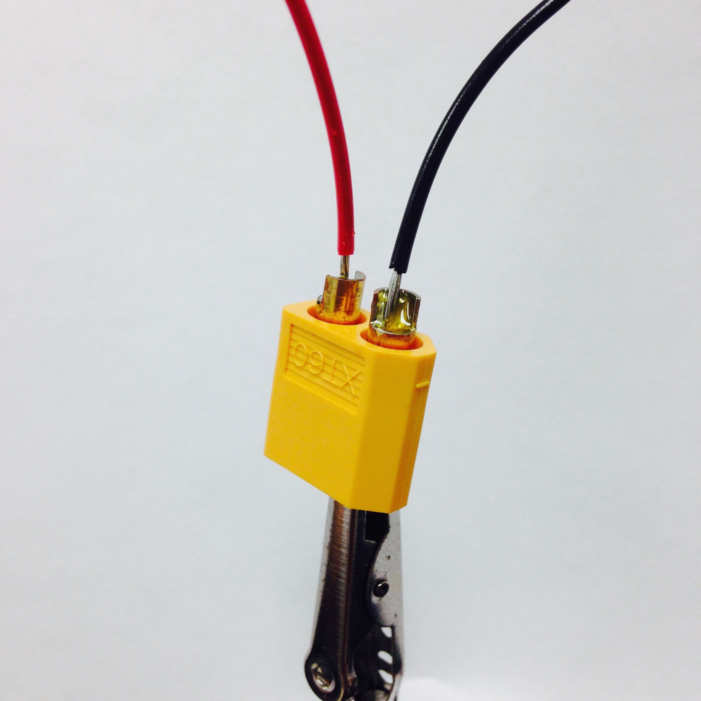
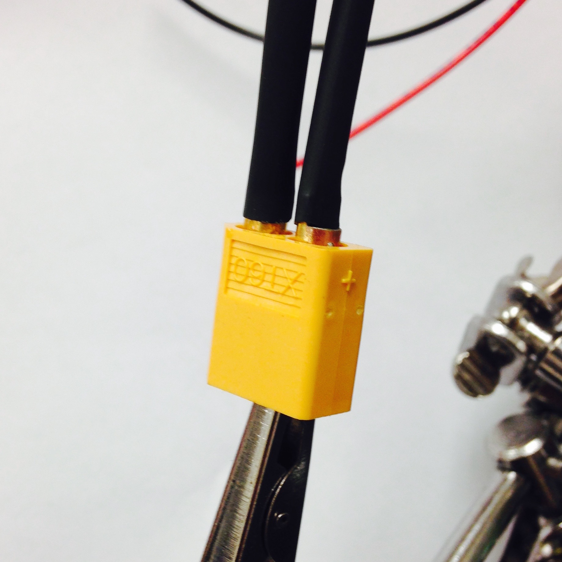
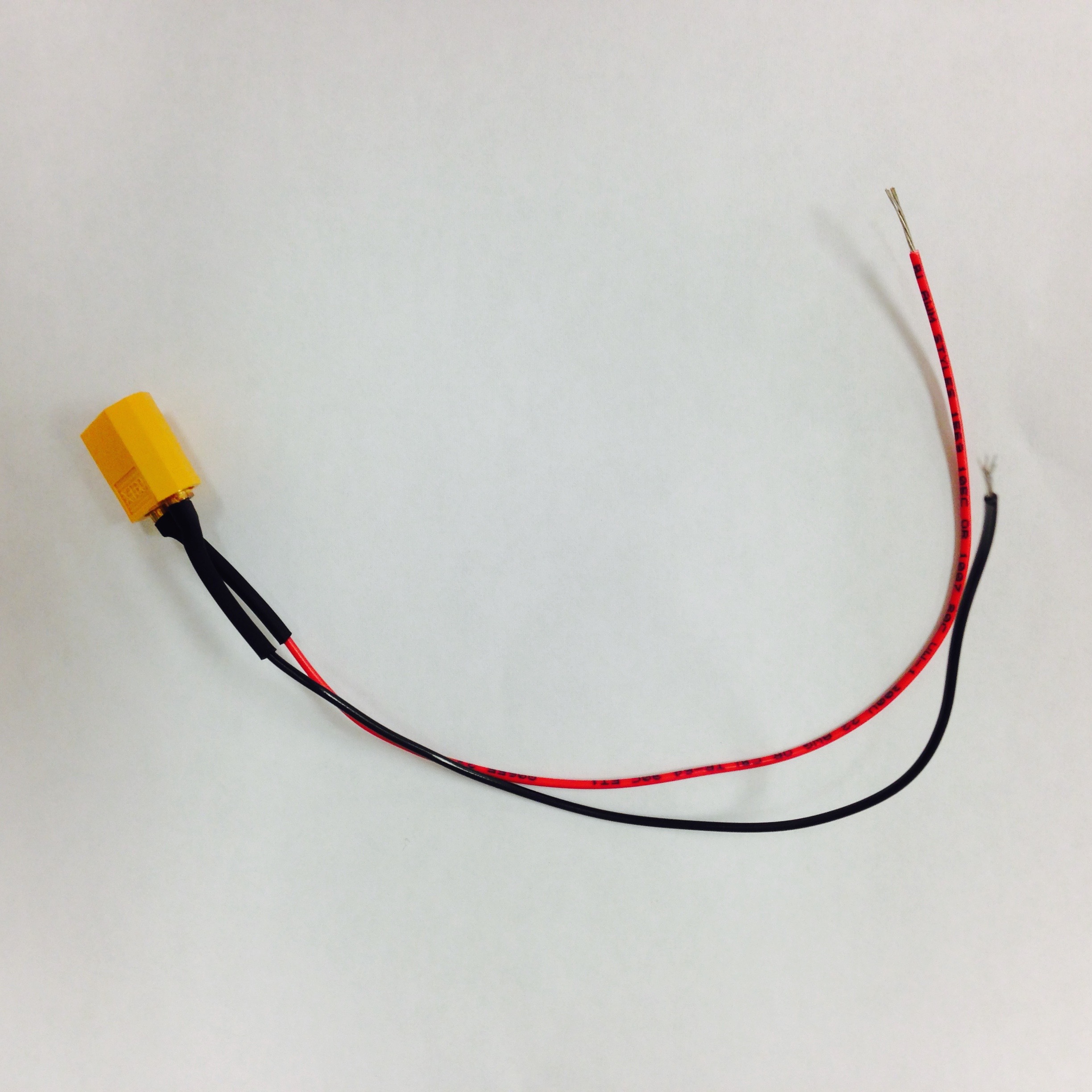
Figure 2.10: Stages of constructing jumper cable.
Chassis Assembly
3D Printing
Most of the robot chassis is 3D printed. These designs were printed on a MakerBot 2X using standard ABS plastic with 12% infill. Other plastics and printers have not been tested though should work. Most of the holes are meant to be self threading screw holes so harder plastics could cause issue here. For the chassis, the following files should be printed.
Core Module
- rear_column3.stl (x1)
- rear_column3_mirror.stl (x1)
- front_column3.stl (x1)
- front_column3_mirror.stl (x1)
- battery_bracket_lipo.stl (x1)
- drivetrain_bracket.stl (x1)
Camera Module
- cameracase_back_tilt.stl (x1)
- cameracase_front_tilt.stl (x1)
- servo_tilt_bracket.stl (x1)
- tilt_bracket_core.stl (x1)
Motor/Encoder/Wheel
The fabrication of the motor/encoder/wheel assembly requires some of the most precise soldering necessary in the course of constructing Pheeno. The first step is to gather the parts and understand their function and behavior. The parts for assembly can be seen in Figure 3.1(a) (Note: This picture does not contain all of the female connection terminals). The $50$:$1$ micro gear brushless motor is very small with a small extended motor gear shaft out of the back which will be used for the encoder readings. The magnetic encoder PCB consists of the small green board and associated magnet; this PCB relays voltages to the motors and records the rotations of the extended gear shaft using Hall sensors. The ribbon cable connects the encoder to the main PCB on Pheeno.
As seen in Figure 3.1(b), carefully solder the ribbon cable to the encoder board. The cable should be soldered to the text side of the board, with the brown wire soldered in the hole labeled GND. If you are using different colored wires, make sure the wires are connected the same way as displayed in Figure [3.1](pheeno_construction_content#fig3_1a). In addition, the wires should bend away from the center of the board, to allow the magnet room to rotate. The board itself can now be soldered onto the motor. The wires should run away from the motor chassis and the words stamped on the motor should be on the same side as the wire leads, as seen in Figures 3.1(c) and 3.1(d). Two pins atop the motor fit into the large holes in the board. Make sure the board lies flat and parallel to the motor when soldering. A trick to do this is to solder one terminal then keep it warm such that the solder is still liquid and reposition the board with pliers. BE CAREFUL NOT TO BURN YOURSELF DOING THIS! YOU DON'T NEED TO USE YOUR FINGERS YOU CAN USE PLIERS! I AM NOT RESPONSIBLE FOR YOU TOUCHING LIQUID SOLDER OR THE IRON!.
Attach the magnet on the motor shaft above the encoder, leaving a little bit of space for free rotation. Typically, the magnetic disc can be put on the extended gear shaft and pressed to a flat surface. The wheel, consisting of the plastic well and a separate tread can be pushed onto the main motor shaft, as seen in Figure 3.1e. Lastly, the end of the ribbon cable should be crimped with female connectors that will be inserted into the Molex 6-Pin female housing. Crimp six 22-30 gauge connectors onto the ends of the ribbon cable. If one considers the cable from left to right with the ground wire (brown) on the left, then the white female connector should fit on the wire with the tabs facing into the table. It is crucial that the female connector fits on in this orientation, attach the six 22-30 gauge pins accordingly, and reference Figures 3.1f, 3.1g, and 3.1h.
Repeat all of the steps above to make the second motor assembly.
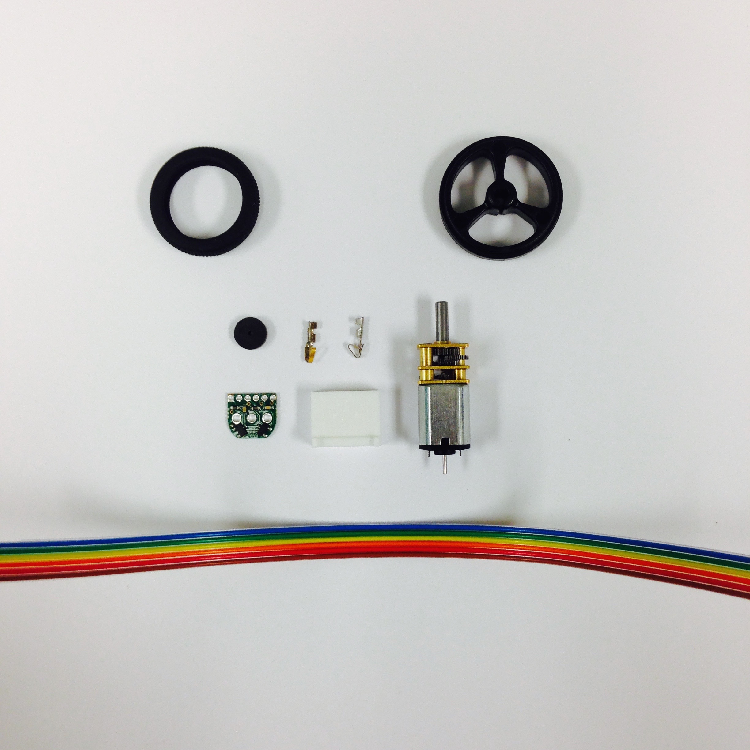
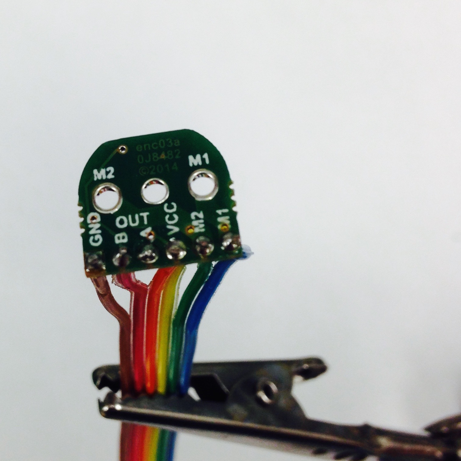
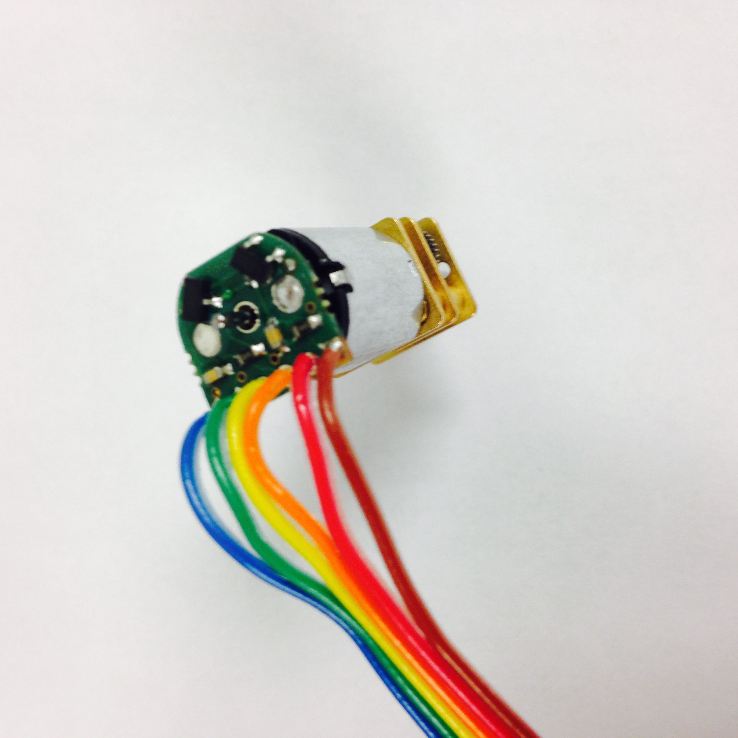
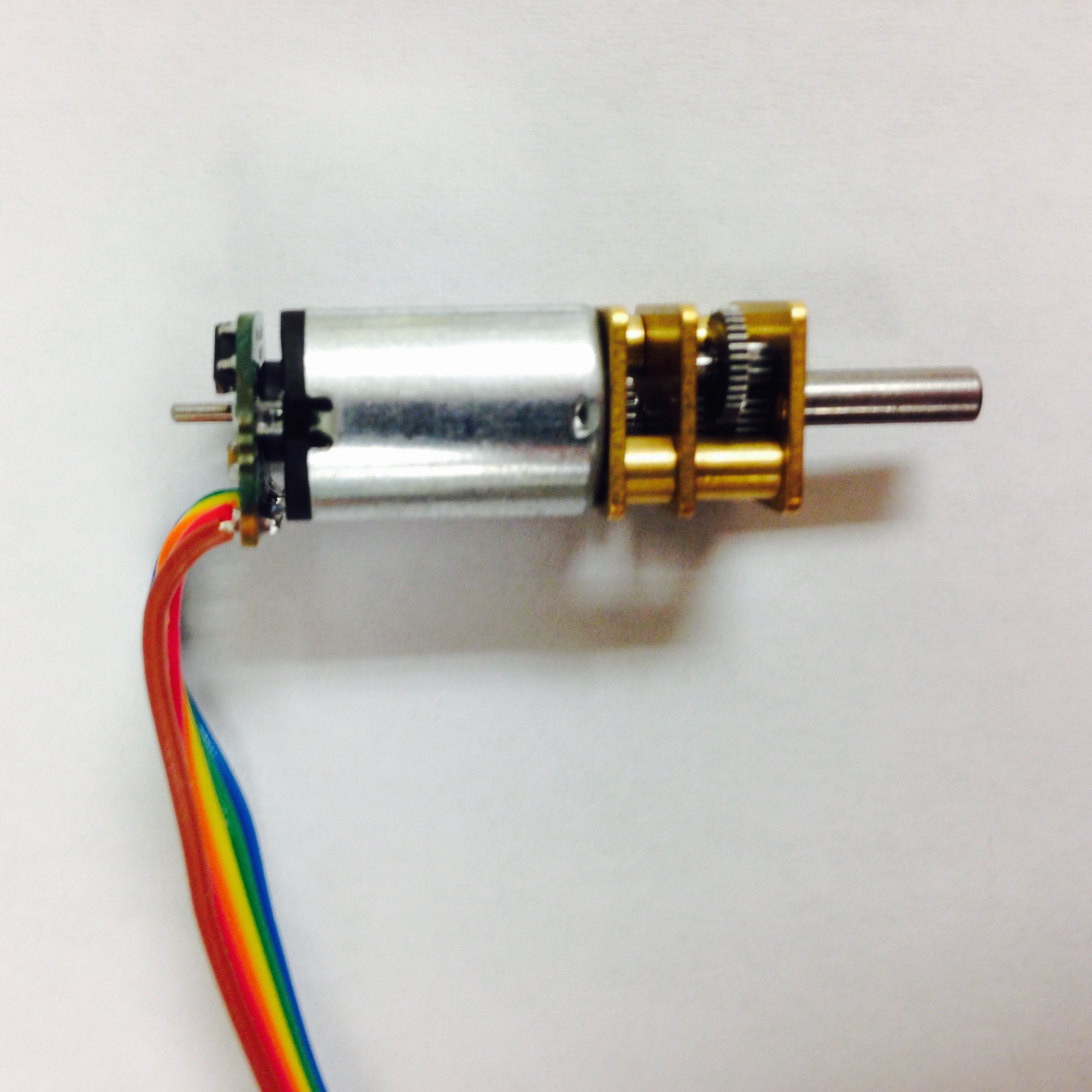
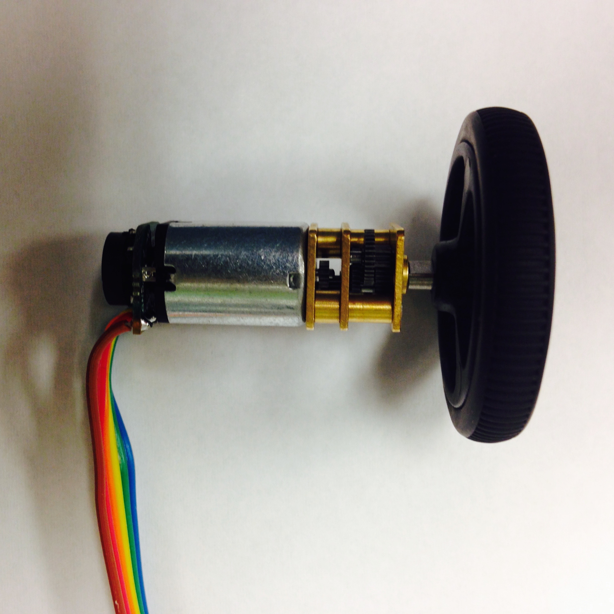
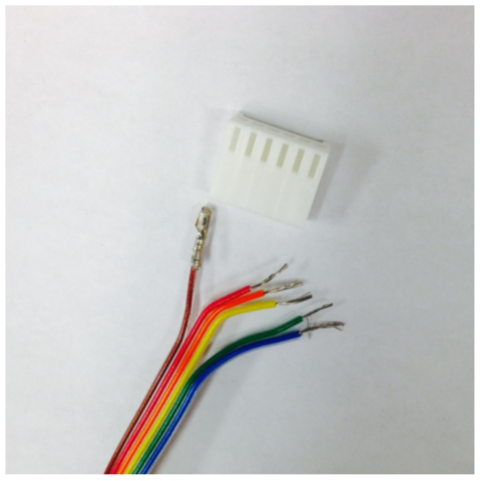
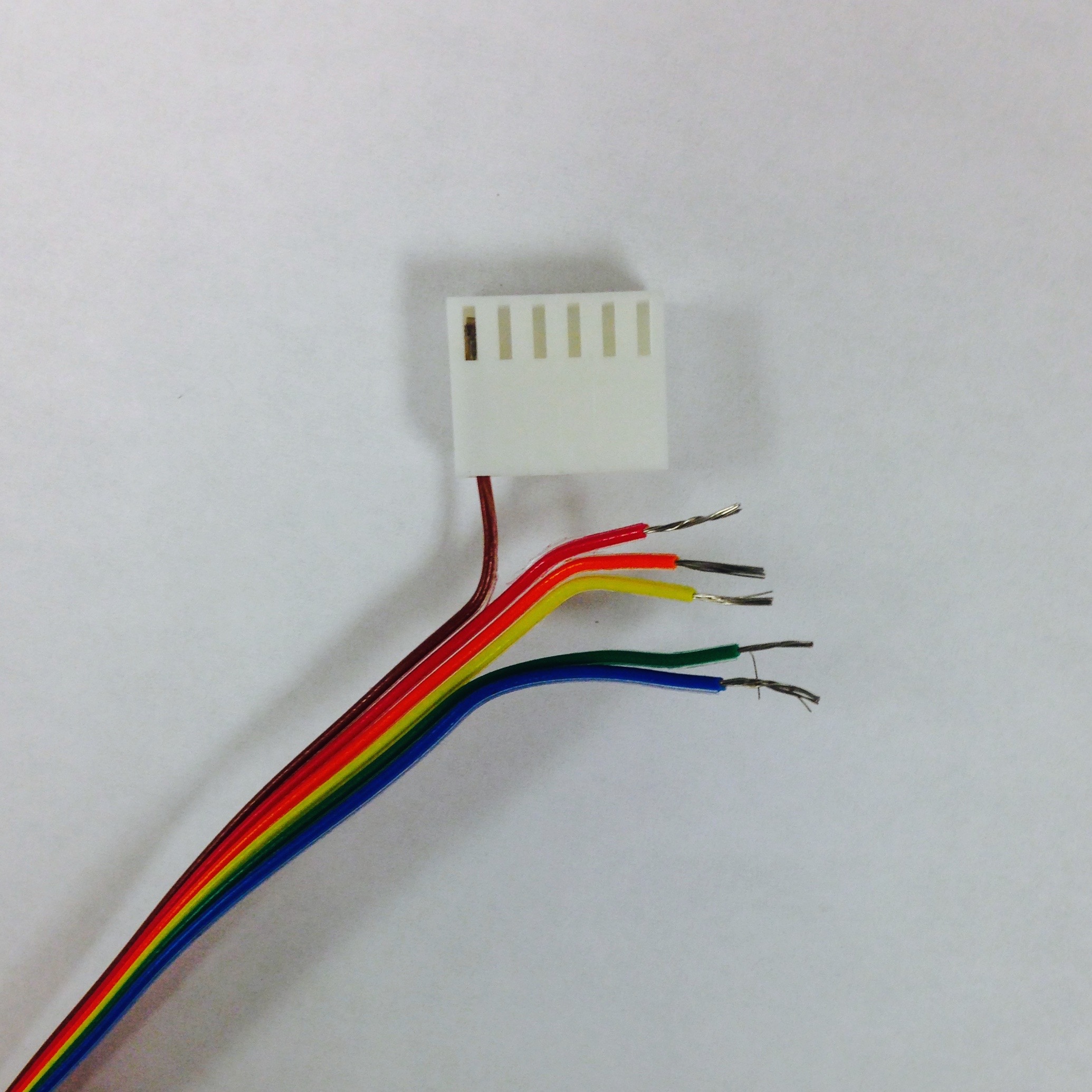
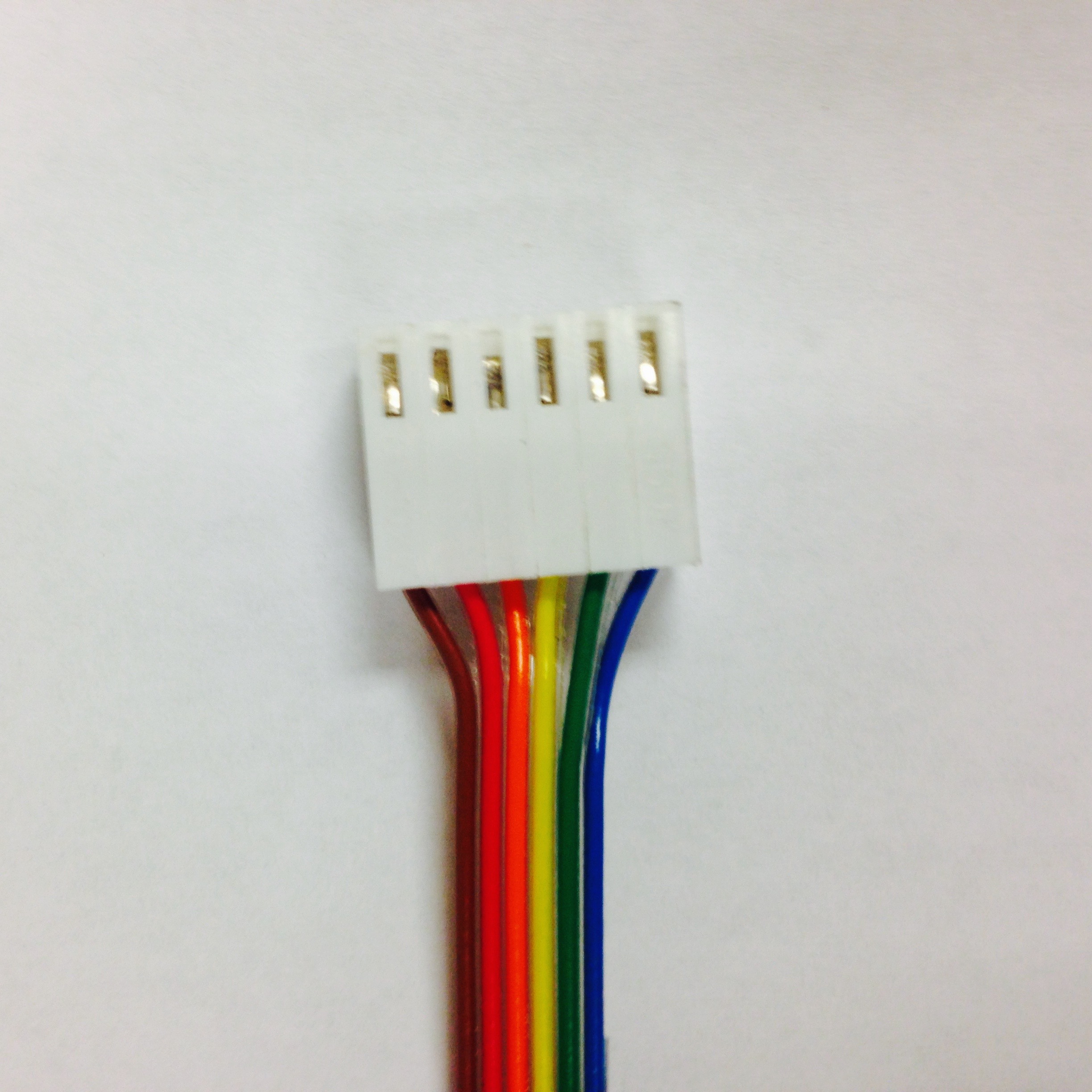
Figure 3.1: Steps for constructing wheel sub-assembly.
Drivetrain
Now that the two motors are complete, they can be mounted to the chassis. Using a 3D printer, print the cross-shaped chassis component. Once the part is finished, make sure to remove the raft from the printed component; this extra bit of extruded plastic is not part of the mechanical design. Ream the holes to clear excess plastic.
Gather the other necessary components. Two caster assemblies are needed in addition to the two wheel assemblies just created. The parts are shown in Figure 3.2(a).
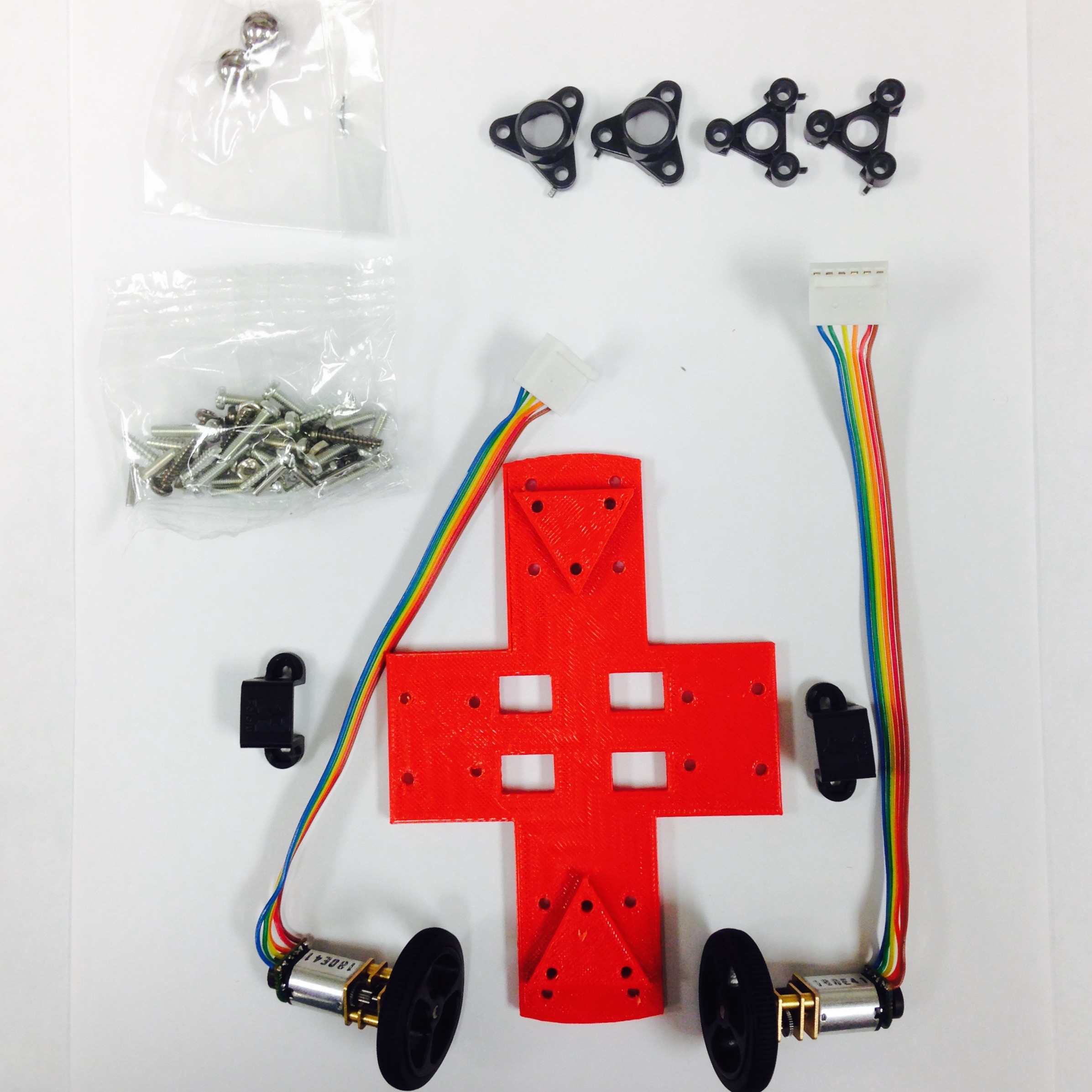
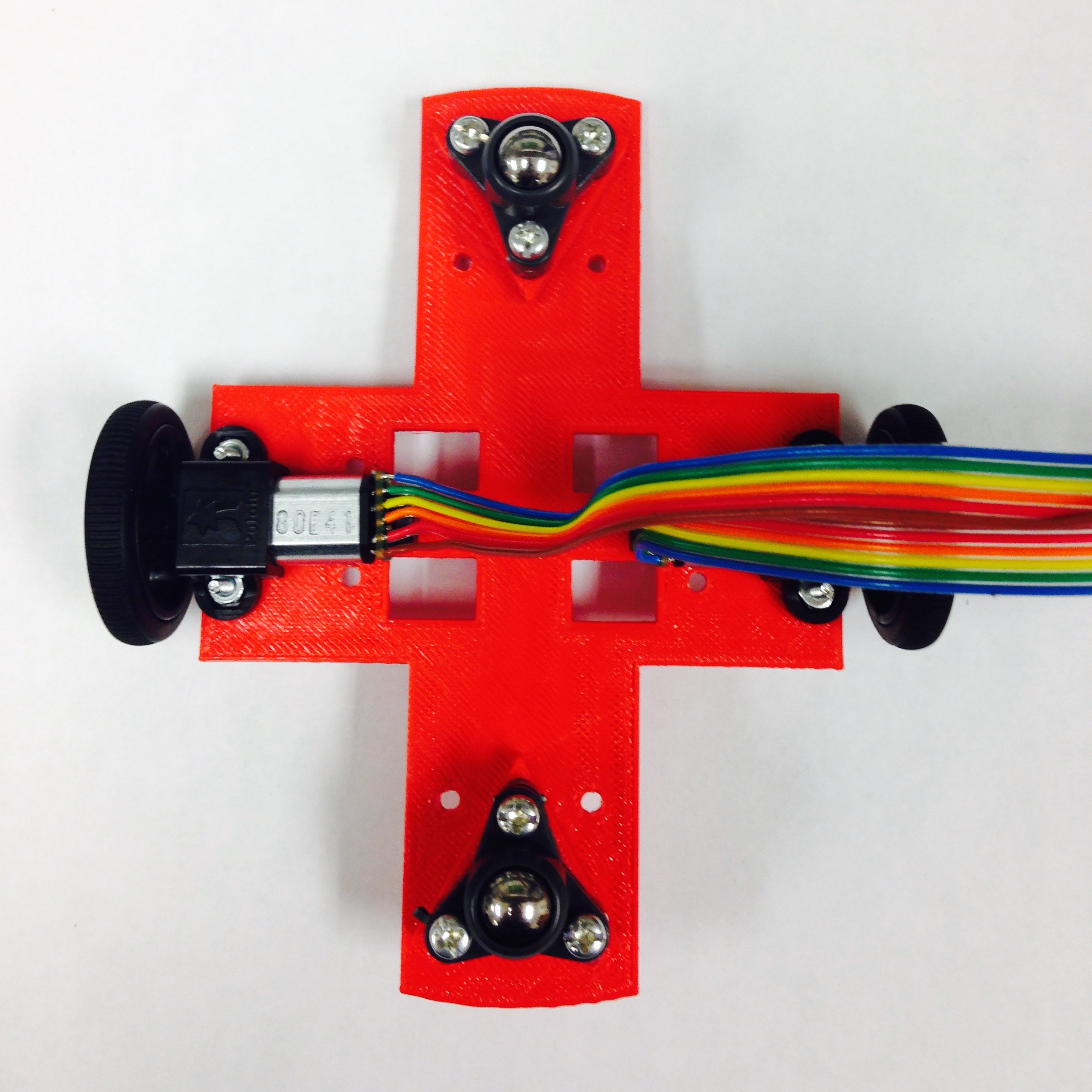
Figure 3.2: Completing the drivetrain.
First, assemble the Pololu casters. The process can be seen in Figure 3.3 and will be referred to through this paragraph. Place the triangular black piece flat on the table with the opening facing out and insert the metal ball, as seen in Figure 3.3(a). Next insert the three tiny metal rods that keep the ball in place, as shown in Figure 3.3(b). Lock the loose components in with the flat triangular piece, shown in Figure 3.3(c). The ball should feel secure but still have a full range of motion without resistance. Screw the assembly onto the triangular extrusion on the chassis mount, as seen in Figure 3.3(d). Repeat these steps for a second caster, then attach it it on the opposite end of the 3D printed part, shown in red in Figure 3.3(d).
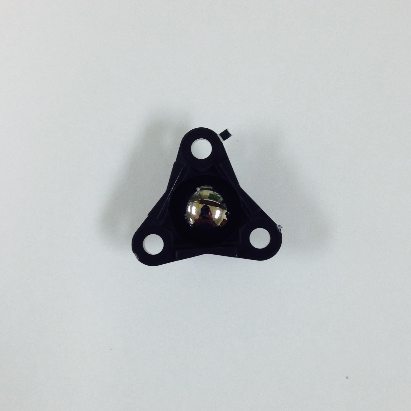
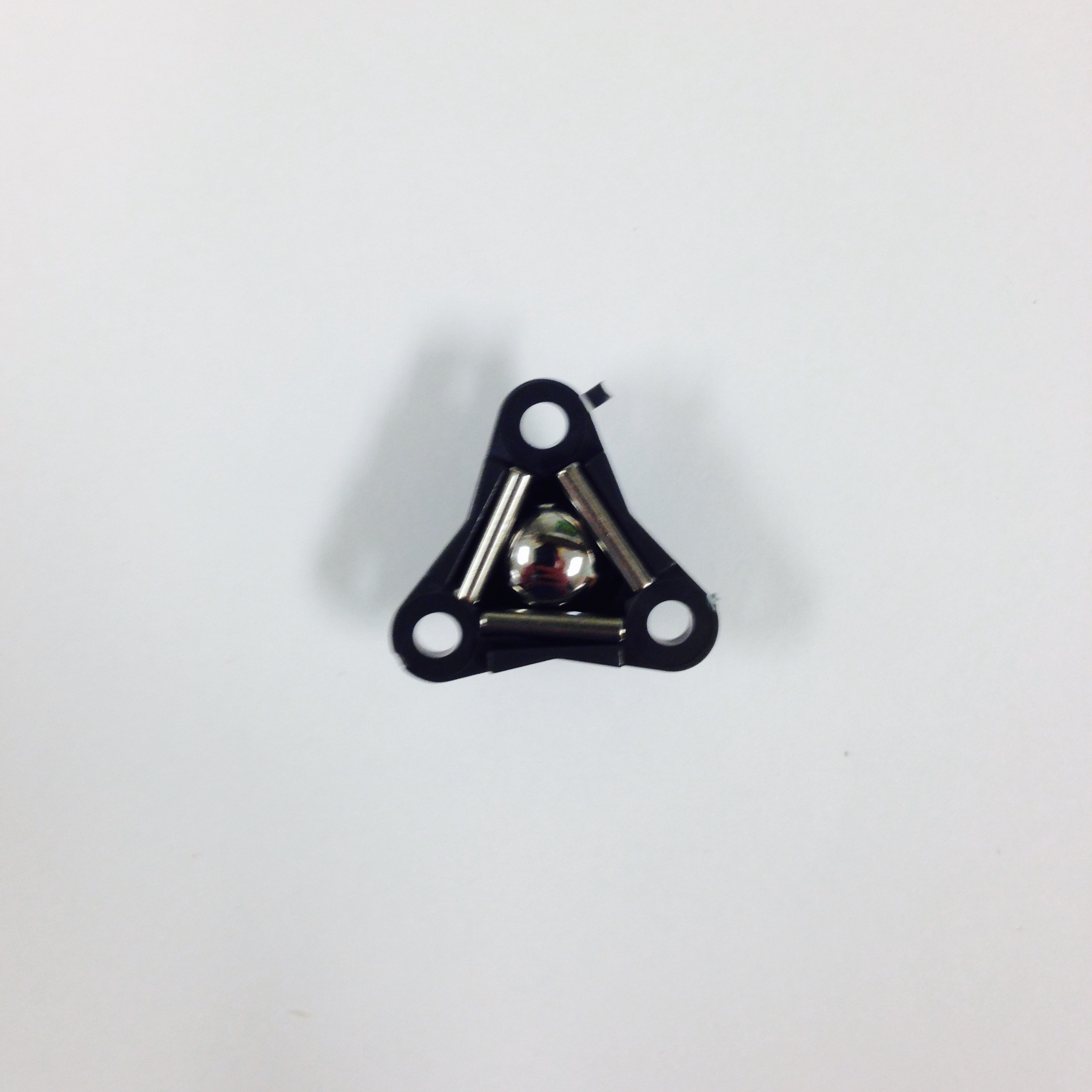
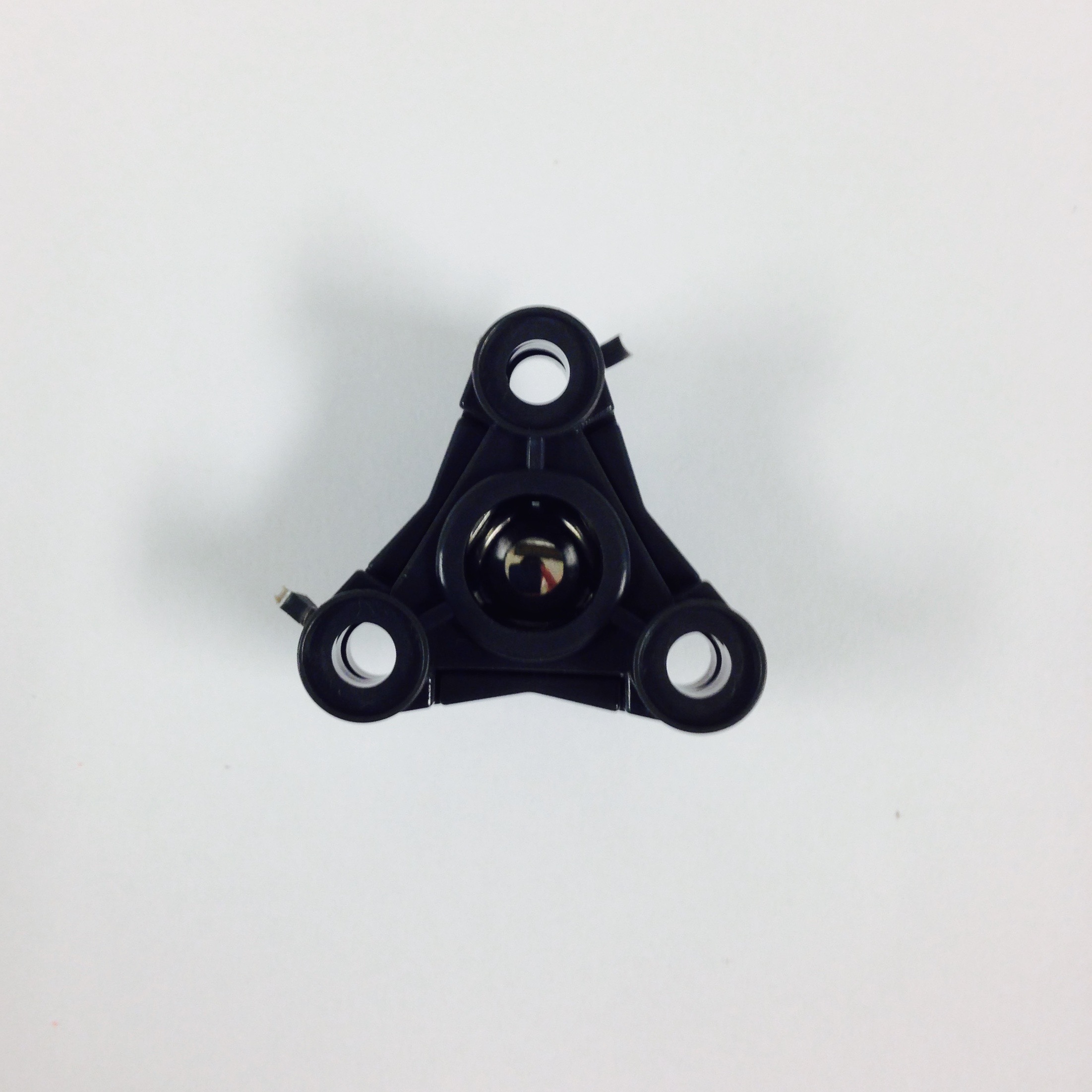
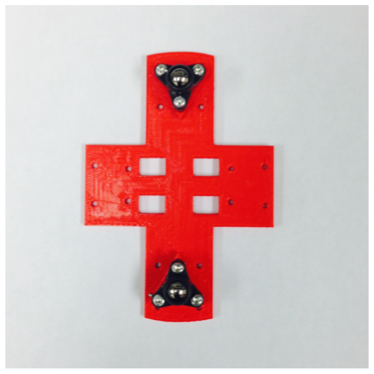
Figure 3.3: Constructing and mounting the casters to the drive train.
The motors will be mounted next. The parts required can be seen in Figure 3.4(a). Each bracket should fit snugly on the exposed gearing portion of each motor. This bracket aligns with the holes on the edge of the chassis piece, so place the tiny nuts in the hexagonal slots in the bracket and screw the bolts in. As seen in Figure 3.4(b), the flat edge of the encoder should be facing away from the cross-shaped chassis. Figure 3.4(c) displays the entire set-up with both motors mounted.
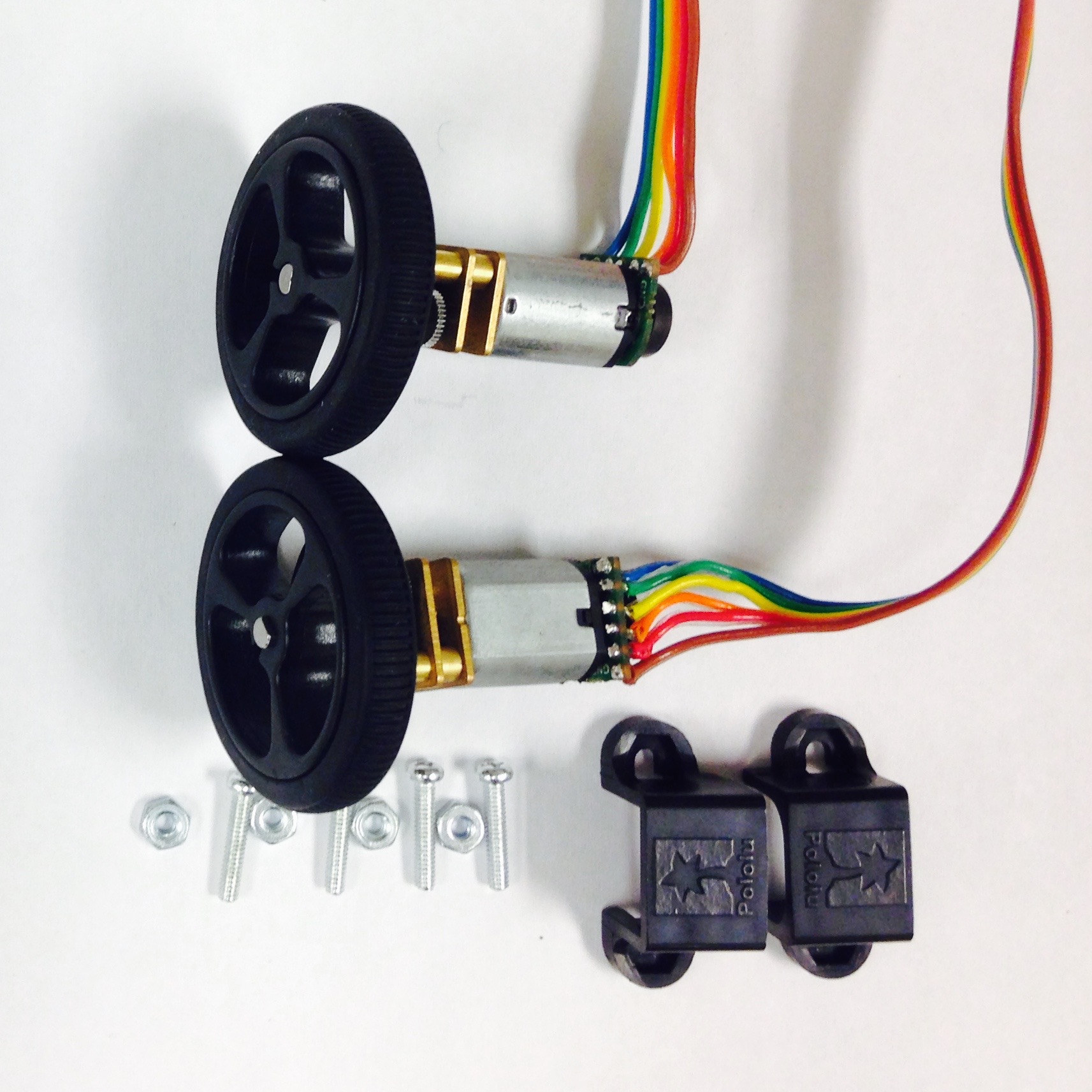
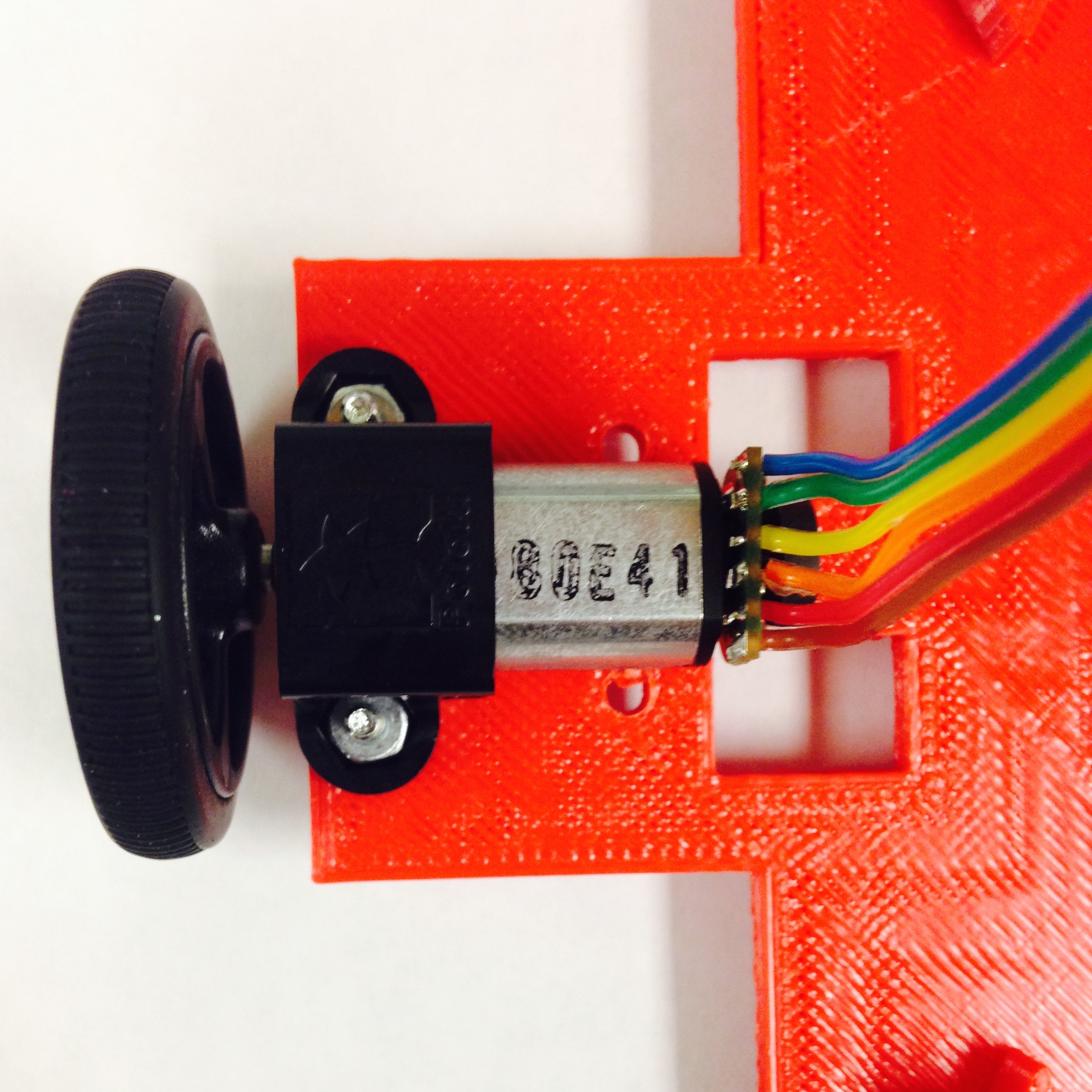
Figure 3.4: Attaching the motors to the drivetrain.
Mounting
We are close to being done with the chassis and full assembly! The only two components left are the Pheeno base board (a laser-cut acrylic disc with slots in it), and the 3D printed battery bracket. Note that the bracket can be rather fragile, so take care not to snap off the protruding tabs!
The base board is sandwiched between the drivetrain assembled previously and the battery bracket. These parts are shown in Figure 3.5(a). There are four holes that align in each of the three components (two in the middle and two at the front of the bot); screw a bolt through each of them to attach the three components. Unfortunately, due to 3D printing errors, these holes frequently don’t align within a very feasible tolerance, so feel free to ream out the holes as necessary. Figures 3.5(b) and 3.5(c) show the bottom and top of the assembly when it is put together.
As seen in Figures 3.5(b) and 3.5(c), the ribbon cables slide through a side slot in the base plate. Make sure that the connectors end up on the side of the battery bracket with a tab by the opening; the encoders can then more easily be wired to the PCB. Unfortunately the female connectors on the ribbon cables do no fit through the slots well on the acrylic base plate. It is therefore necessary to use a rotary saw (likely a Dremel) to lengthen the slot to fit the connectors through. The final result is shown in Figures 3.5(b) and 3.5(c). Another way to do this is to insert the wires into the 6-Pin Molex connector, as shown in Figure 3.1, after slipping the wire through the smaller hole if you do not have access to a cutting tool.
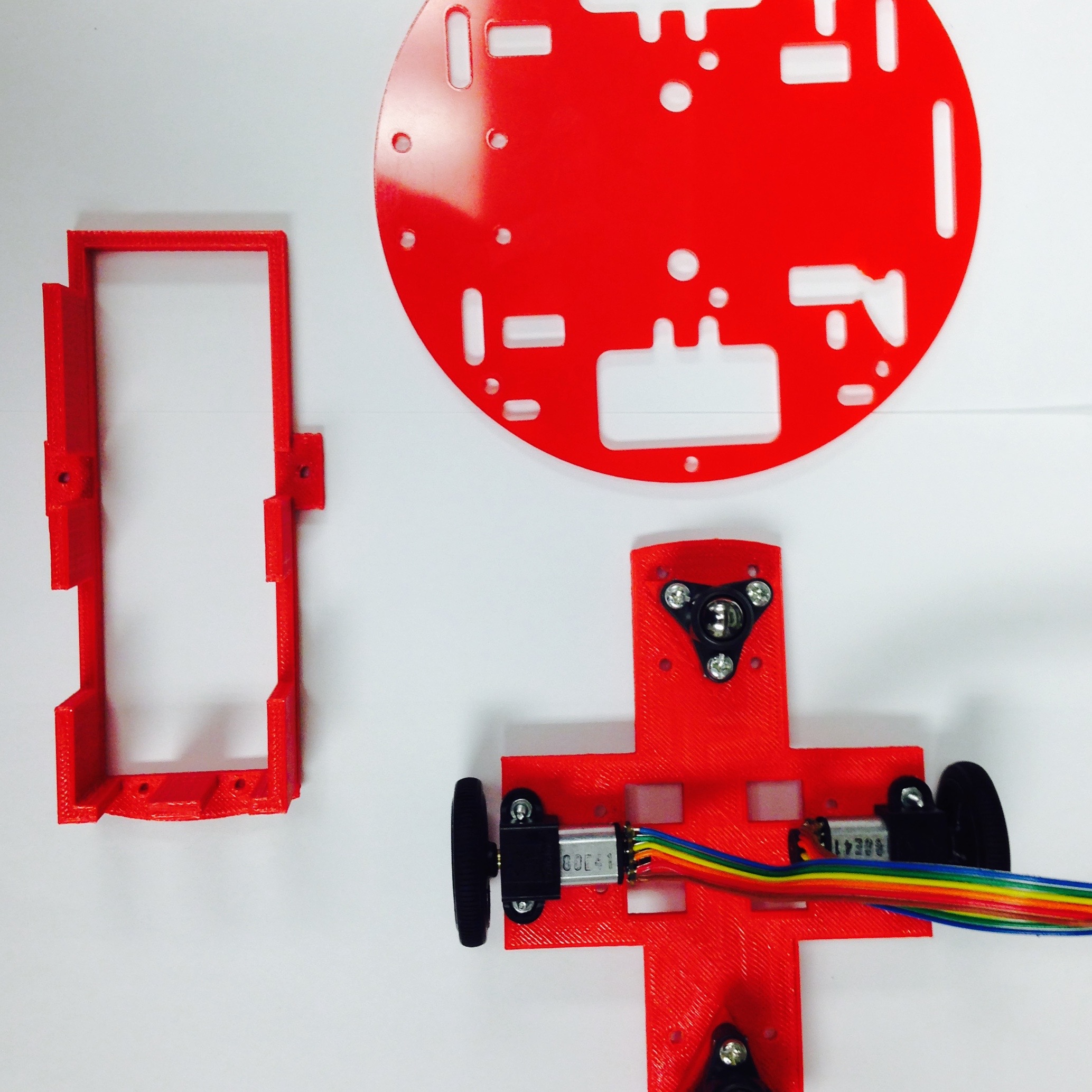

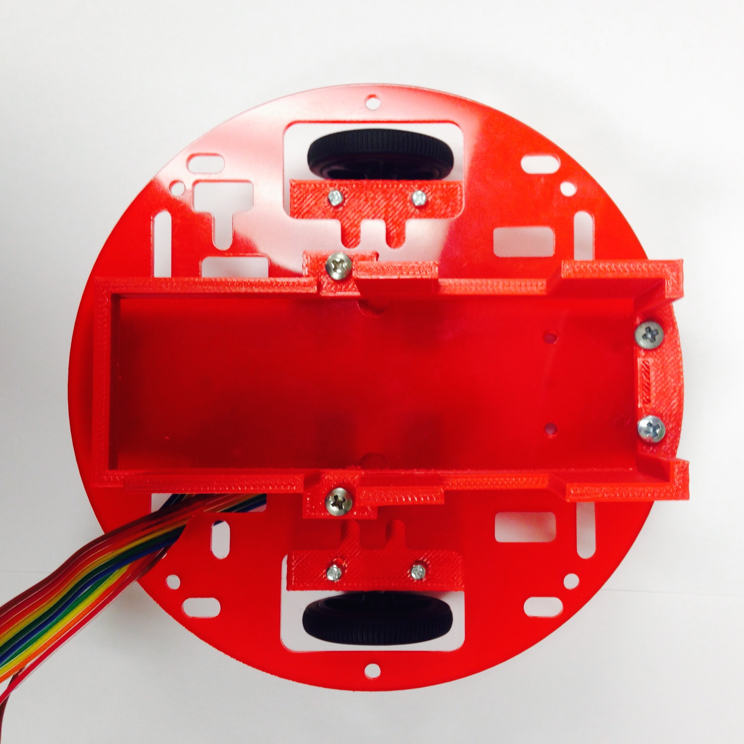
Figure 3.5: The base of the chassis assembly.
Robot Interior
PCB Mounting
The base of the robot is finished, so we can build up from it. The next important stage is attaching the PCB developed in Section 2. The side walls of Pheeno consist of two pair of 3D printed columns. The narrow columns attach in the back of Pheeno, namely the side with the battery bracket opening. The tabs should face inwards and be on the side of the column closes to the back as seen in Figure 4.1(a). The rectangular holes in the column should be near the base of the robot, as seen in Figure 4.1(b). Meanwhile, the wide columns are located in the front of the robot. The wide slots in these columns serve as openings for the IR sensors. These columns should be mounted such that the tabs are facing inwards and towards the front of the robot with the wide opening away from the base of the robot. The finished assembly are shown in Figures 4.1(a) and 4.1(b).
Take the PCB assembled in Section 2 and slide it into the Pheeno with the Arduino positioned towards the front (the columns with the IR openings). The male pins extruding from the bottom of the board should be positioned near the female connectors on the ribbon cable. Screw the PCB onto the tabs of the columns. Be careful not to snap off the mounting tabs by pushing too hard! Do not be concerned if the columns bow a bit, this is normal. Connect the encoder cables to the PCB assembly with each cable oriented on the side its associated motor is located. Namely the ribbon cable from the left motor should slide into to the left-hand male connector, and vice versa. If these are switched, Pheeno will drive opposite the expected direction.
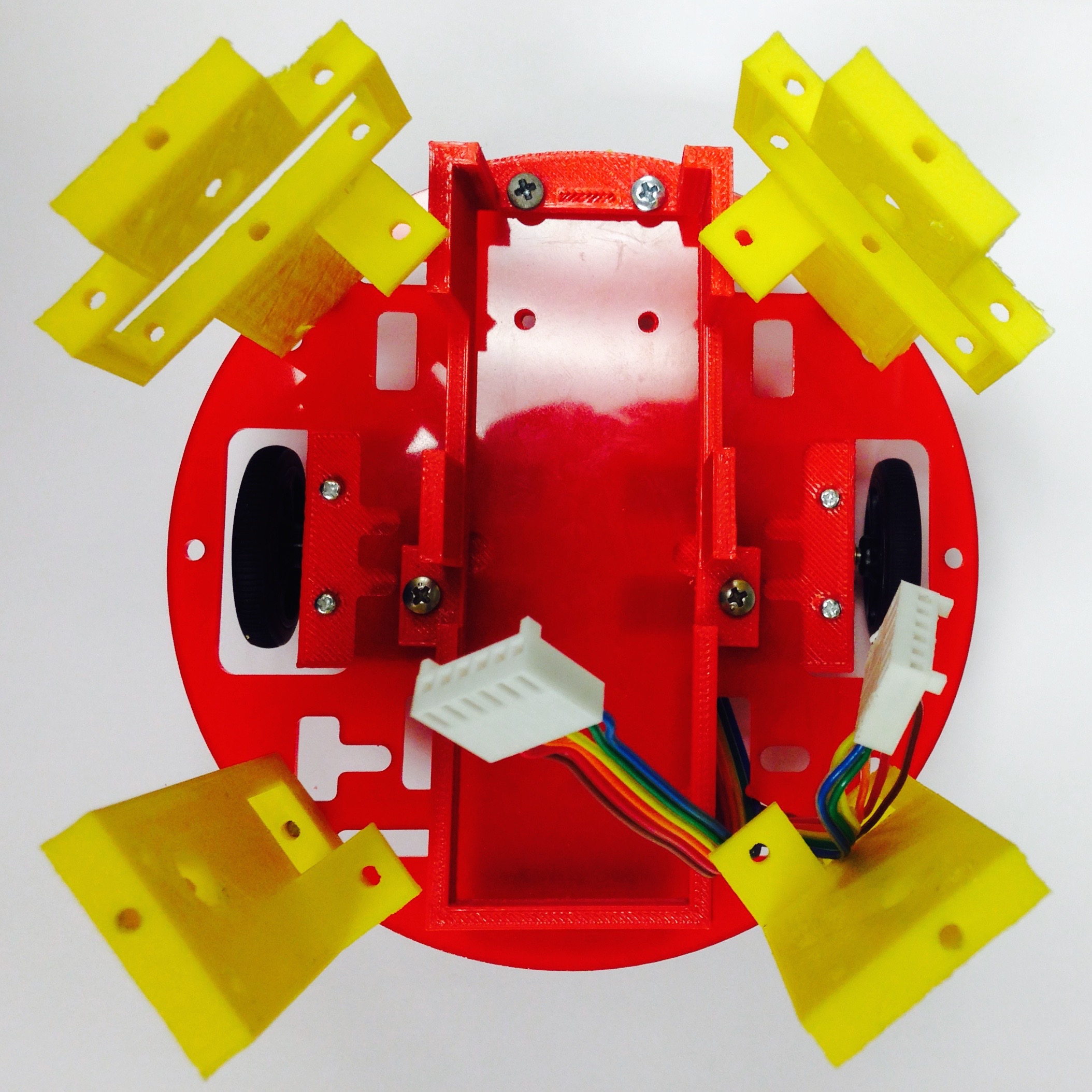
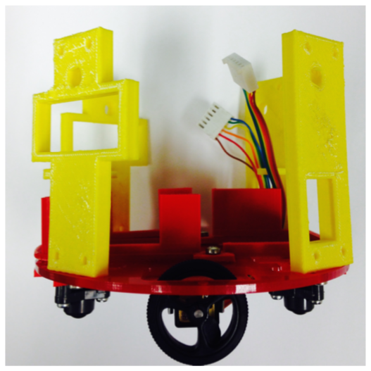
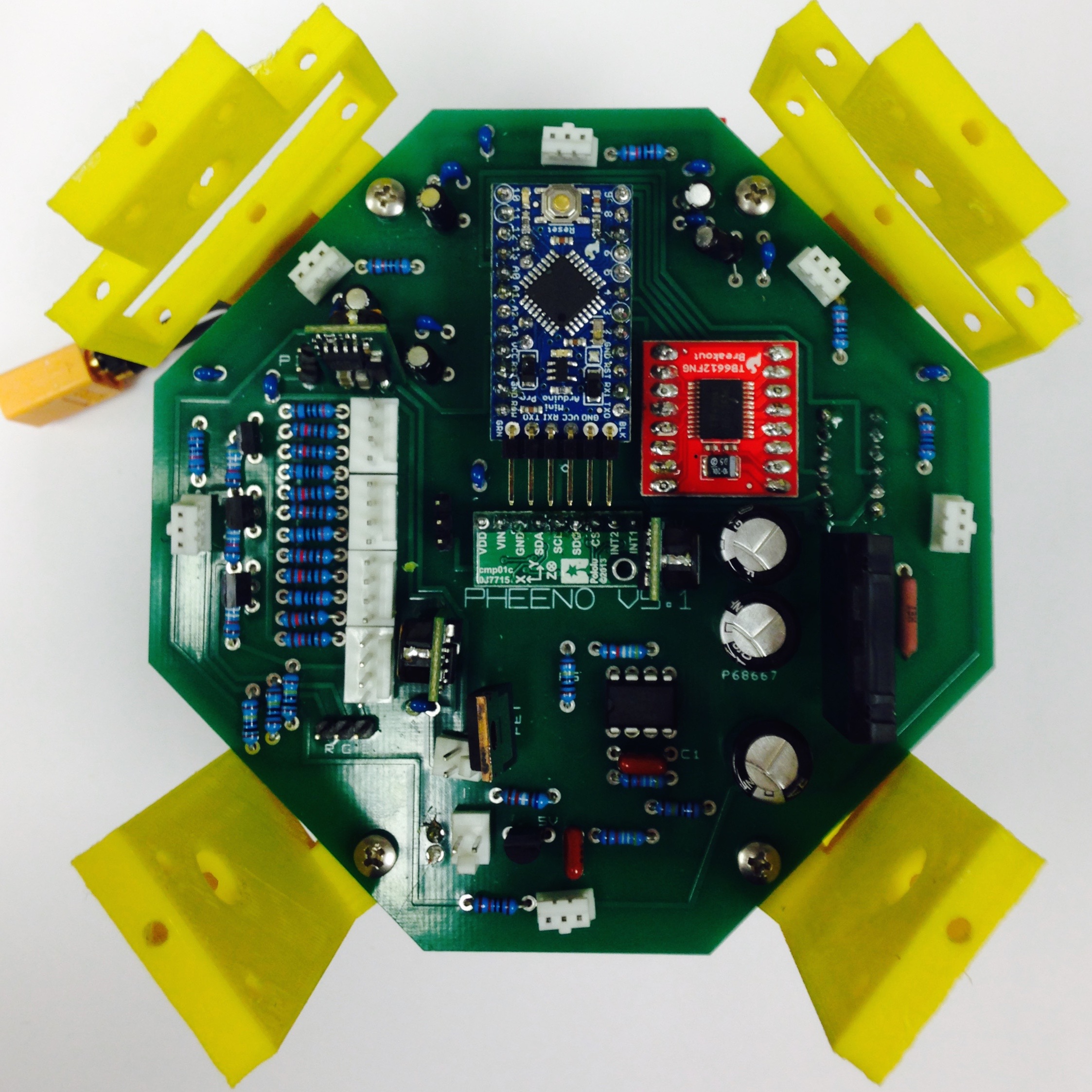
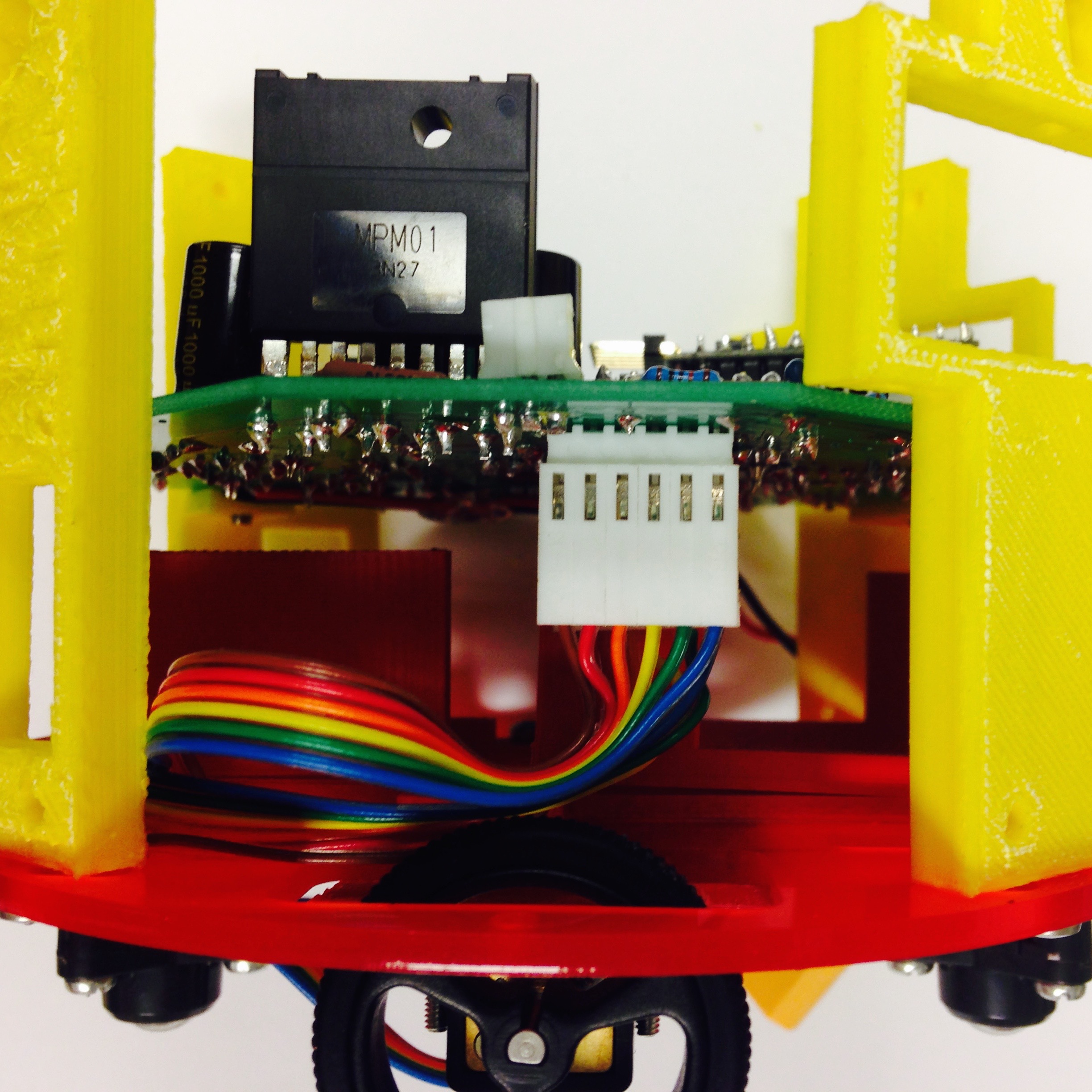
Figure 4.1: Assembly of the interior of Pheeno.
Switch Construction
The square slots in the rear columns can fit an on-off switch for Pheeno. The switch assembly connects to two pins on the PCB and more easily allows for disconnecting the power than unplugging the battery would.
The assemble process is shown in Figure 4.2. The first step is fitting a wire through the hole in the back of the switch, as shown in Figure 4.2(b). Solder this connection (Figure 4.2(c)) and then heat shrink it to insulate it (Figure 4.2(d)). It doesn’t matter which wire connects to which pin; the switch is simply a breakpoint in in the circuit. Repeat the process with another wire for the other pin. At this point the switch should look like Figure 4.2(e). Similar to the 6-Pin Molex connector made in Section 2, Figure 3.1(g), crimp two 22-30 gauge female connector terminal to the opposite ends of the wire. Insert these wires into a 2-Pin Molex female housing as seen in Figure 4.2(f) to complete the switch assembly!
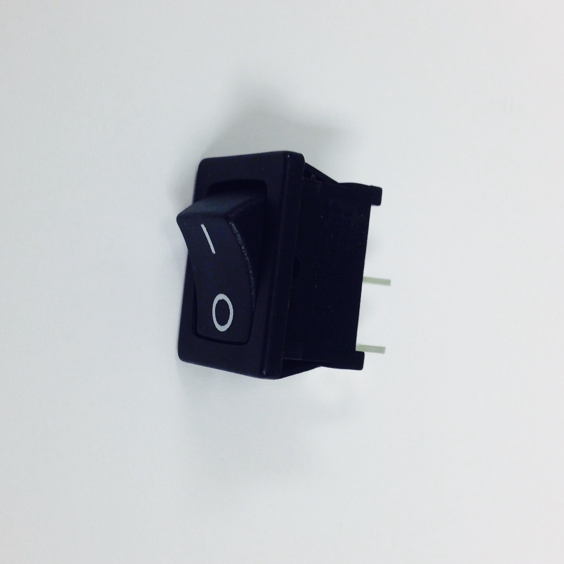
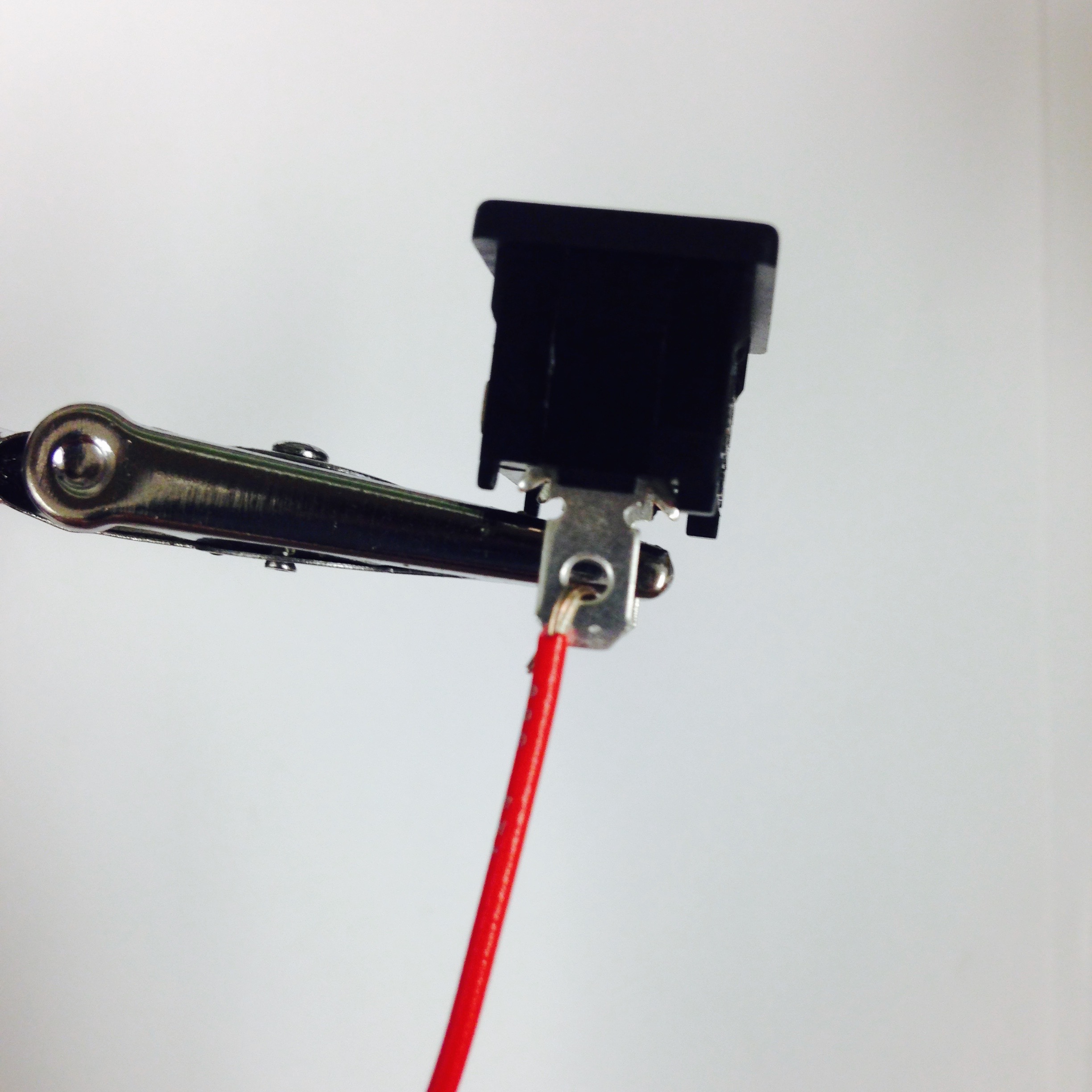
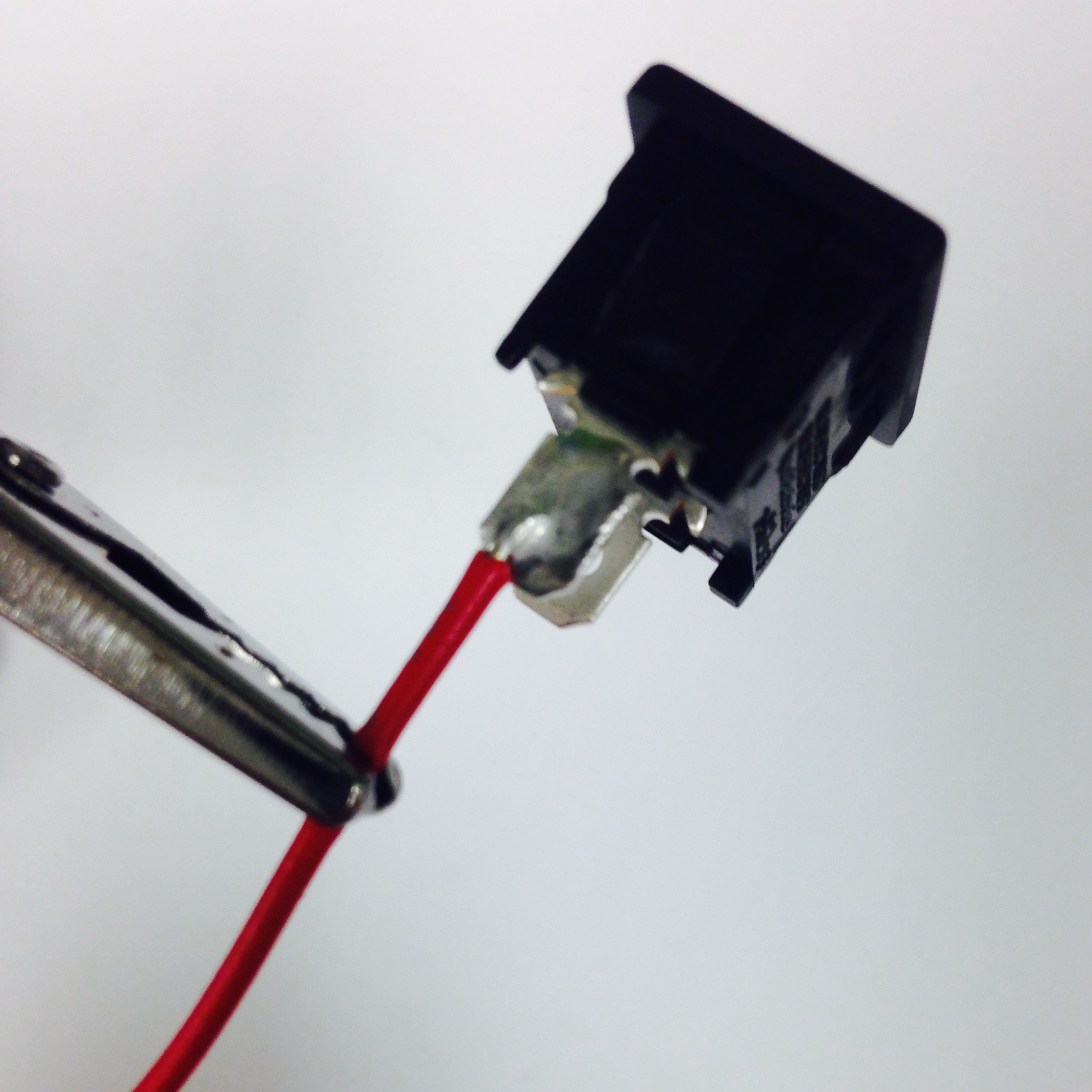
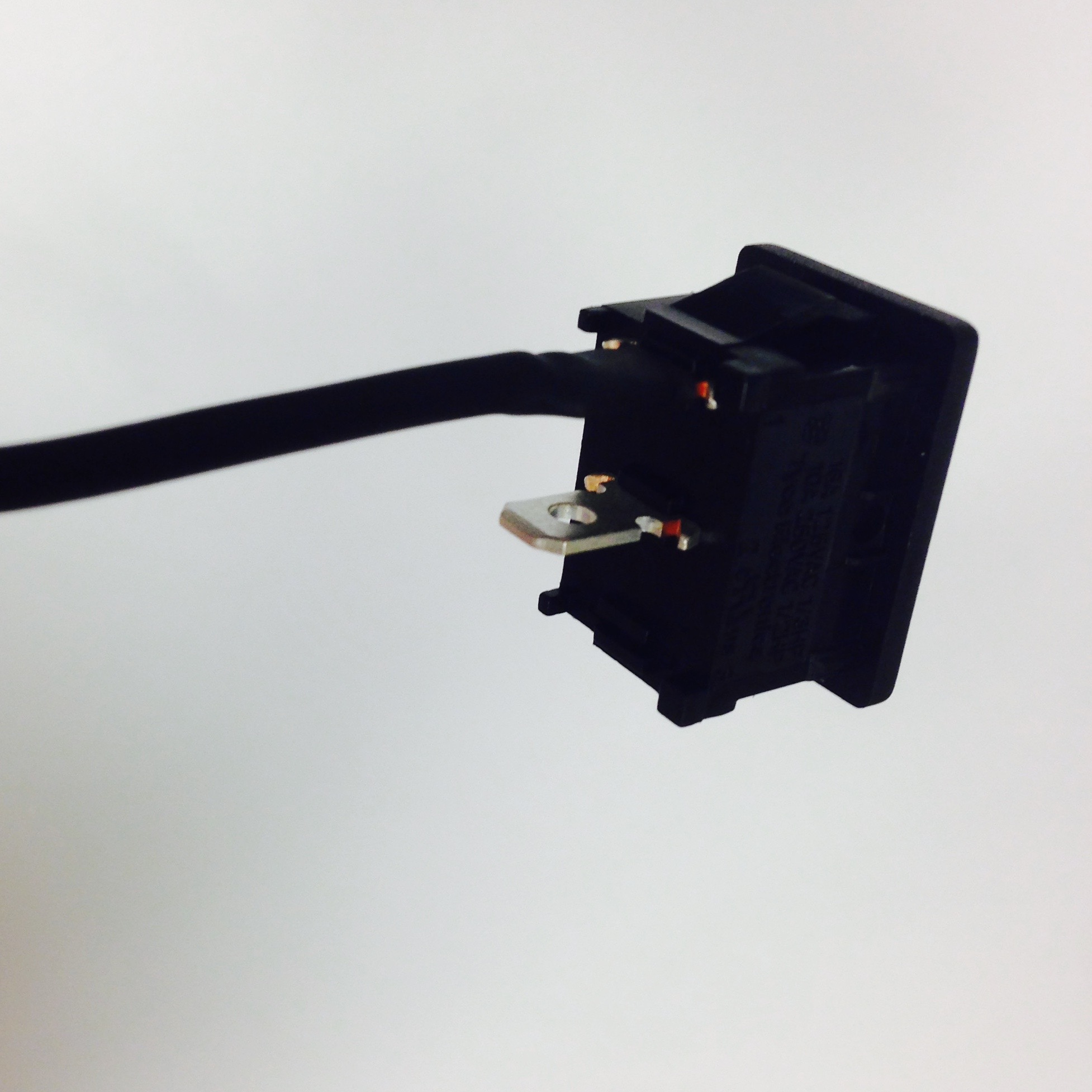

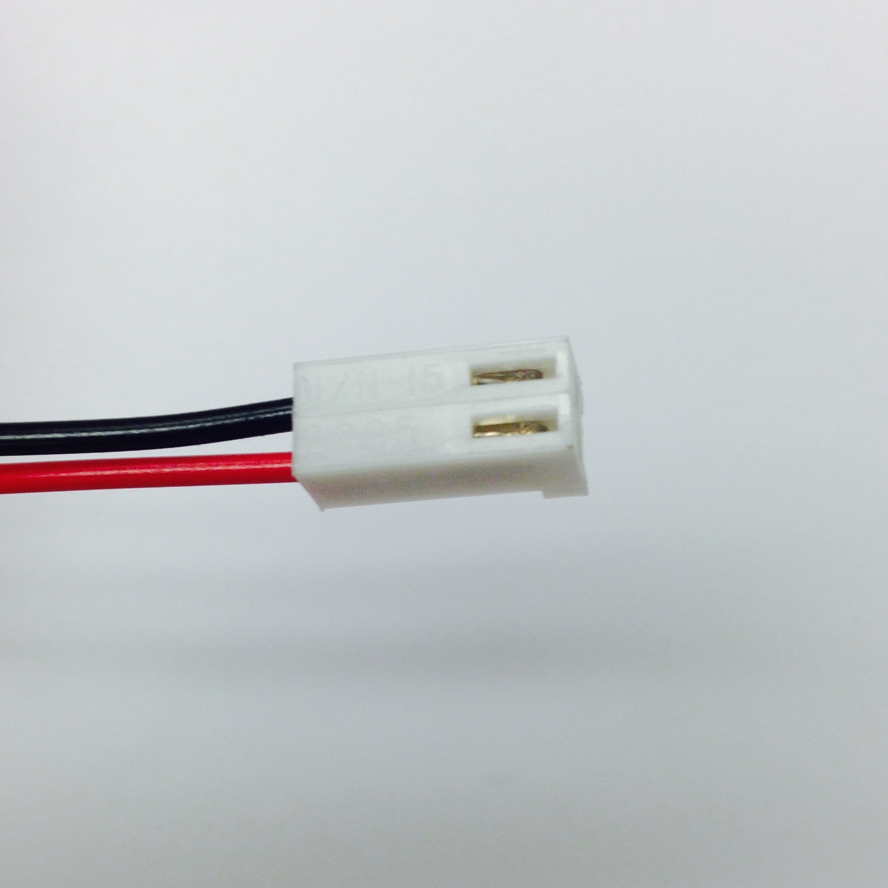
Figure 4.2: Steps for assembling switch wire.
To attach the switch to Pheeno, refer to Figure 4.5. Slide the connector through one of the columns into the interior of the Pheeno. The physical switch should fit securely in the column but can wiggle around and still pop out with enough force. You can secure it further with some hot glue. Run the wire under the PCB and loop it back on top to the pins by the rear IR sensor. Ensure that the connection is at the lower set of pins, as seen in Figure 4.3(b). The switch wire can be run from either column in any secure way to the pins on the PCB, just make sure it cannot block an IR sensor or interfere with any circuitry.
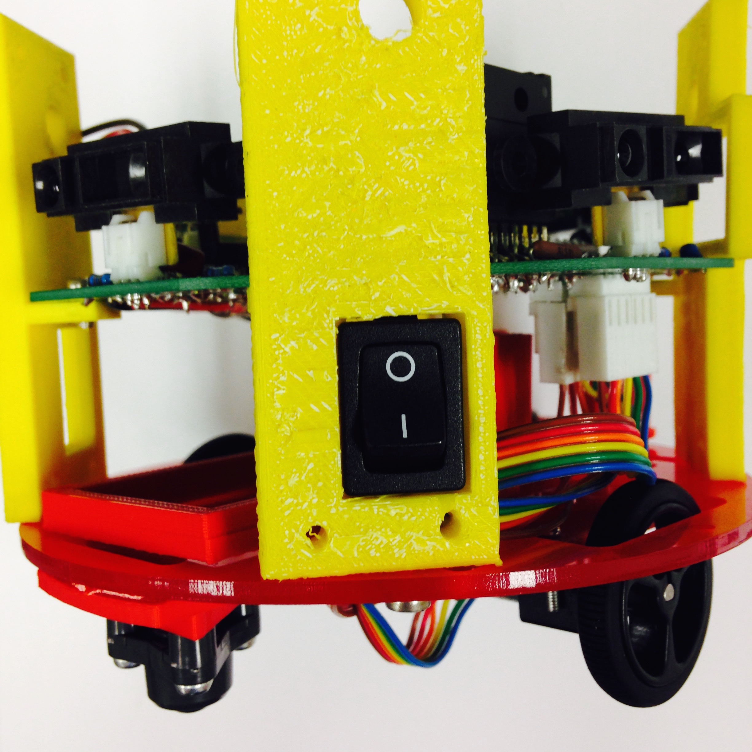
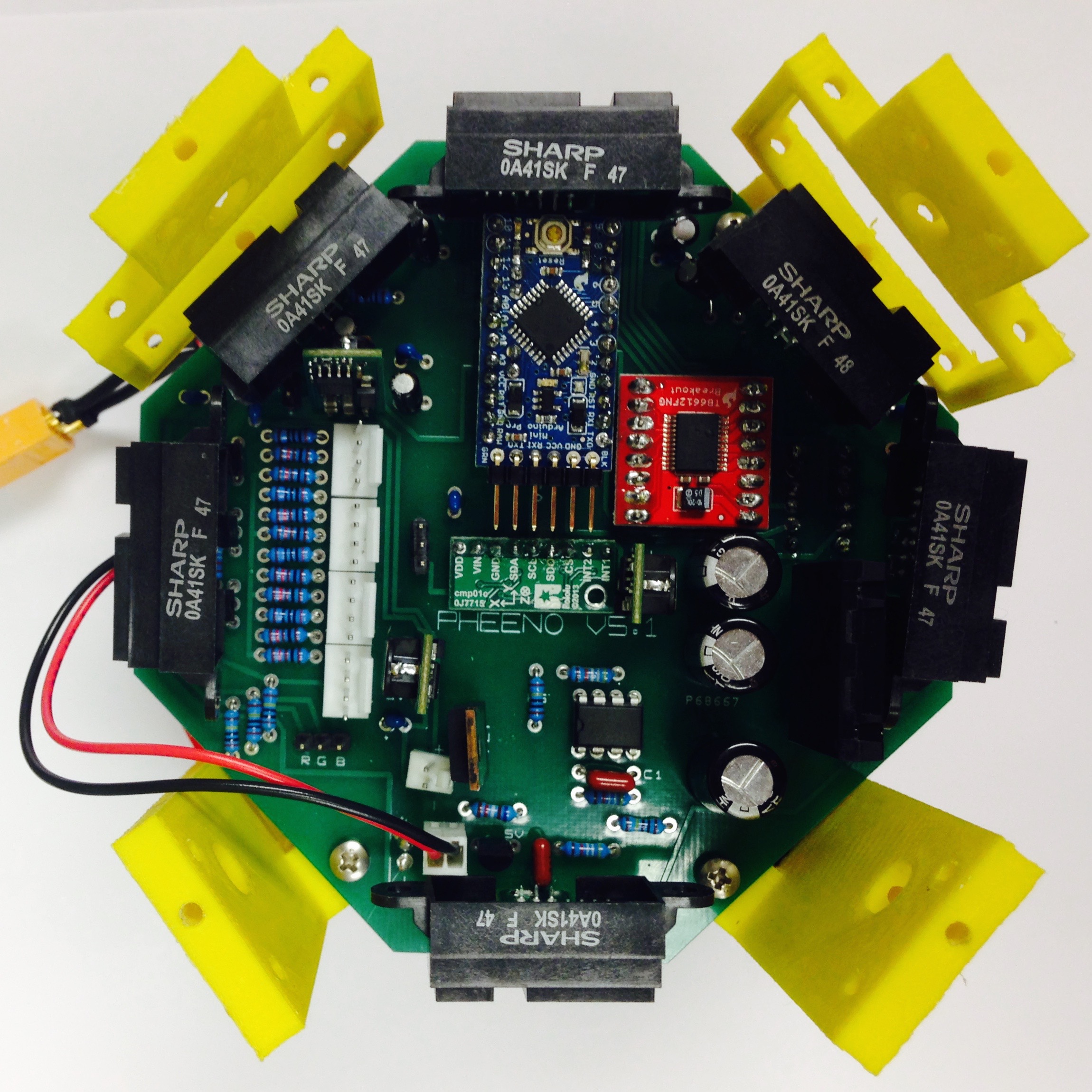
Figure 4.3: Connecting the switch to Pheeno.
LED Construction
A useful user feedback indicator of Pheeno’s behavior, such as driving, gripping, lifting, etc, is to associate each behavior with an LED color. The holes in each column serve as spots for four multi-color, common anode LED’s. Of course, these bulbs need a manner of attachment to the PCB. The construction of this LED sub-assembly can be seen in Figure 4.4.
Take the long lead of an LED bulb and wrap the stripped end of a 3in piece of red wire about it to make a solid physical connection (Figure 4.4(b)). This is a similar technique as if you were soldering two wires together. Solder this connection together by carefully coating the twisted connection (Figure 4.4(c)). Cover the exposed wire with a similarly sized length of heat shrink wrap (Figure 4.4(d)). The result can be seen in Figure 4.4(e). Repeat the process with black wires for the other three leads. The finished result is shown in Figure 4.4(f).
On the opposite end of the wires, crimp a 24-30 gauge female connector onto the exposed metal for each one, ash shown in Figure 4.4(g). Then insert these connectors into a 4-Pin Molex female housing. Note that the orientation of the connector is important; with the tabs pointed towards the table the first two wires should be black, and the third red! This orientation can be seen in Figure 4.4(h).
Repeat the process for three more LED sub-assemblies.
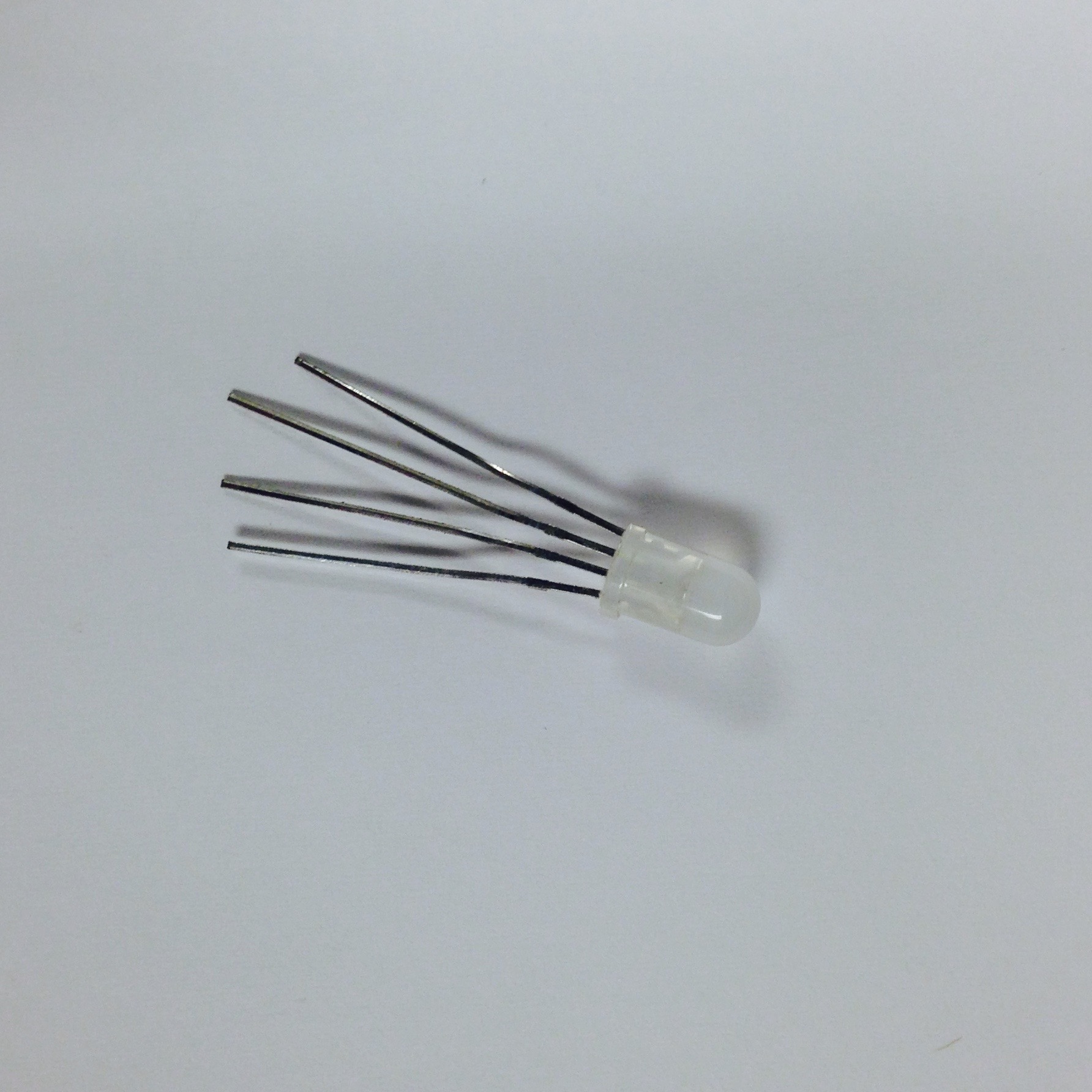
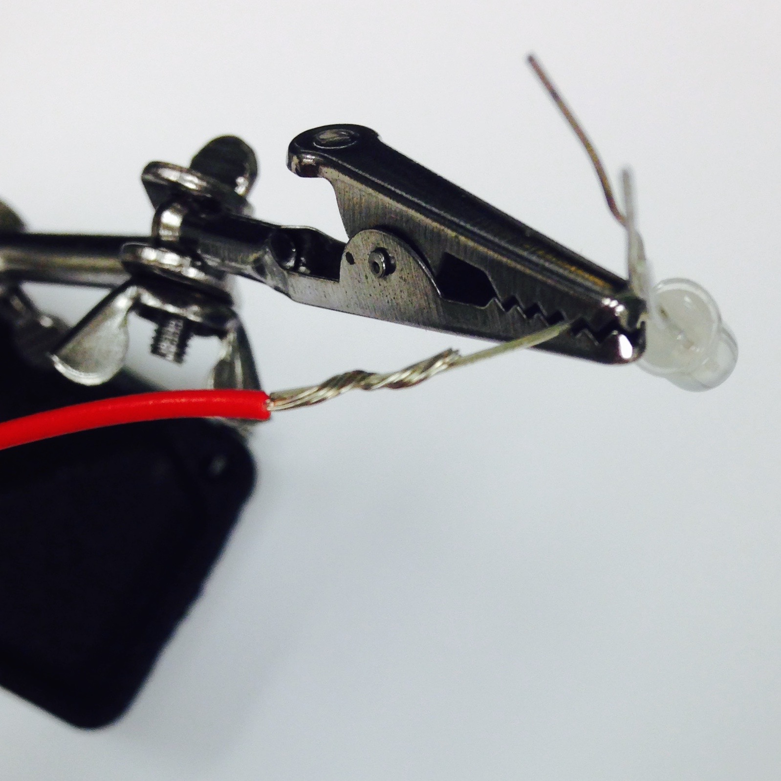
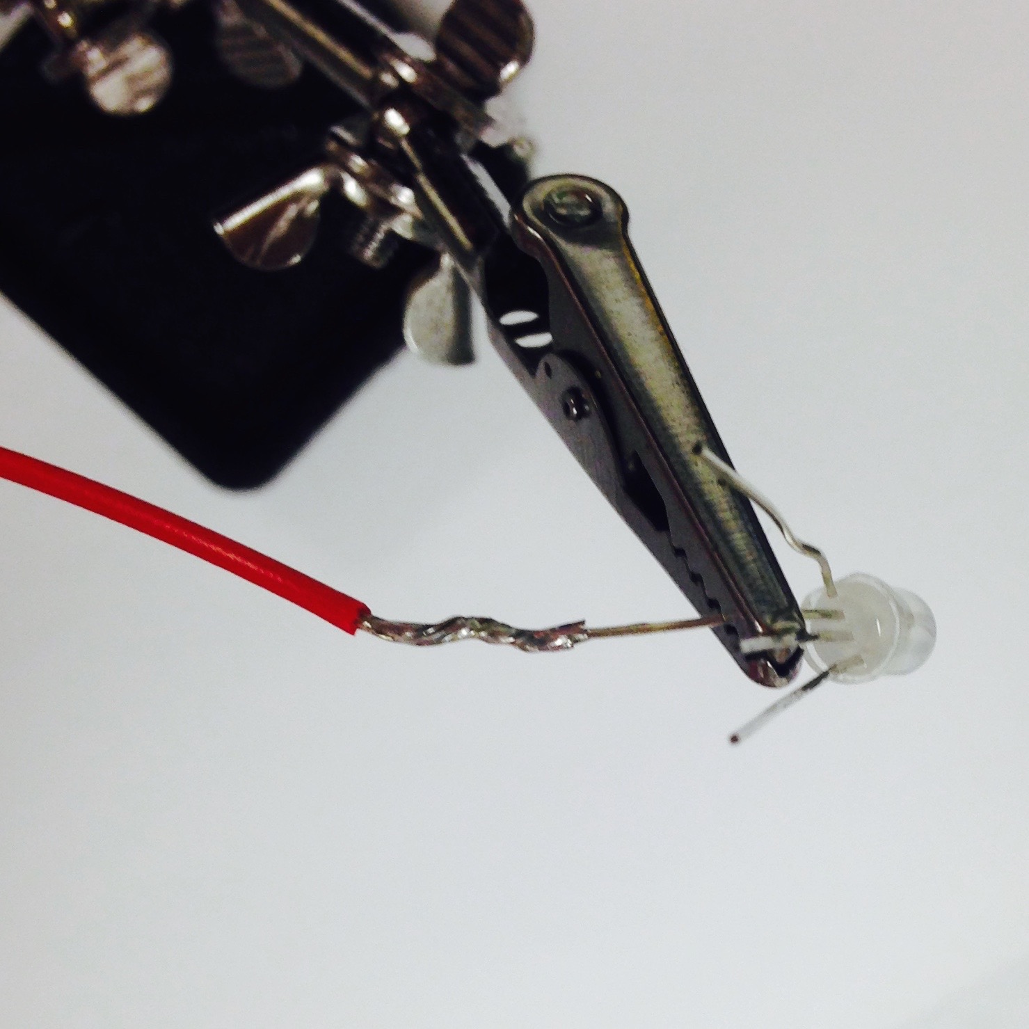
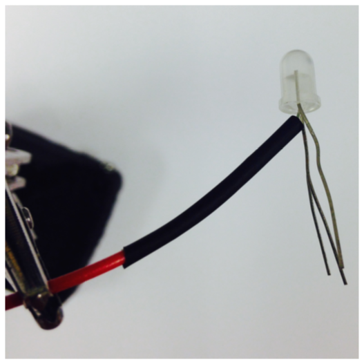
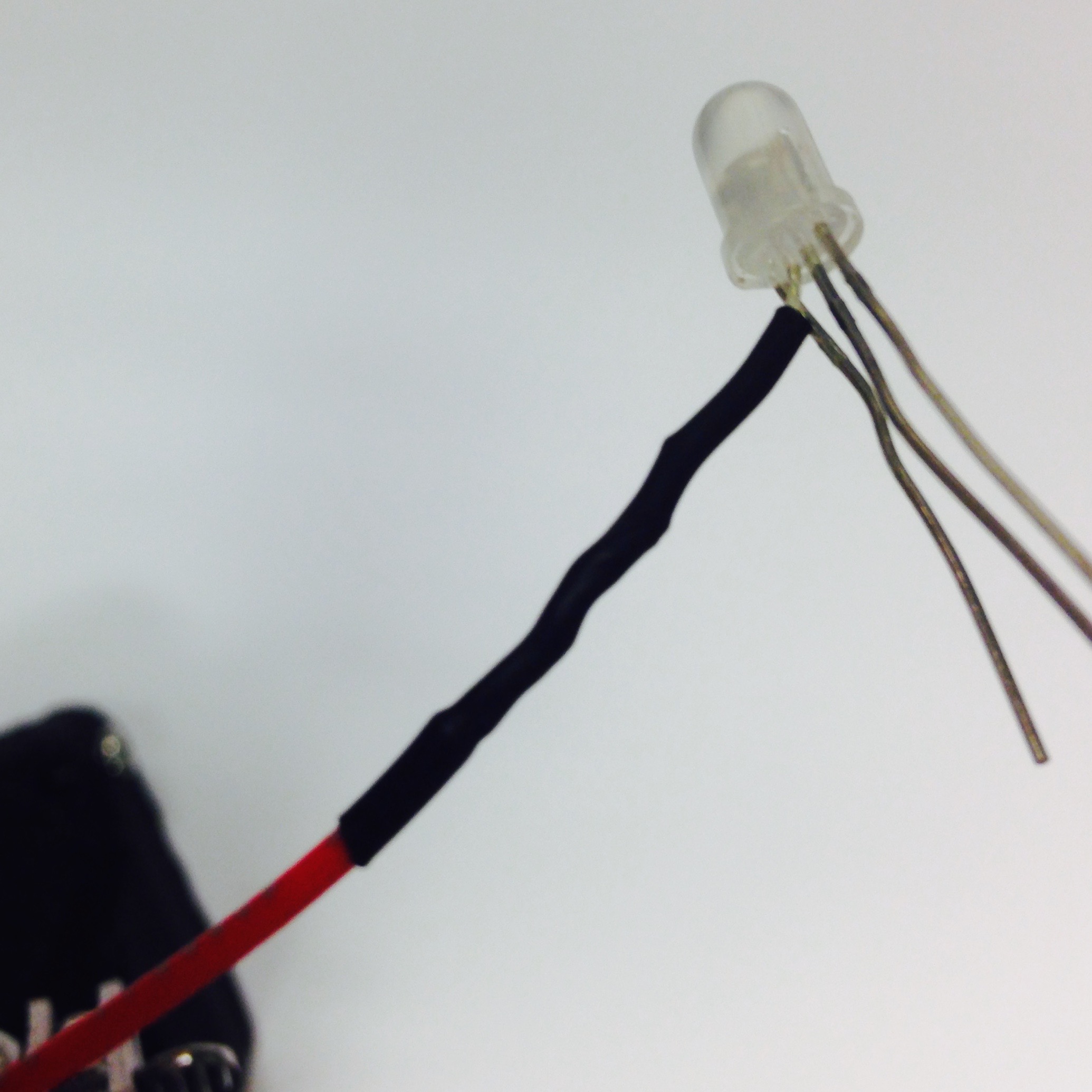
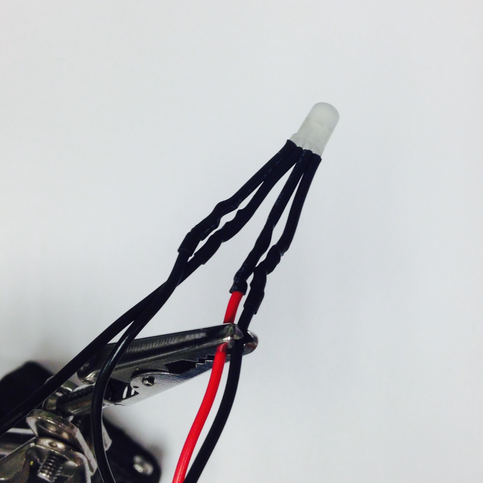
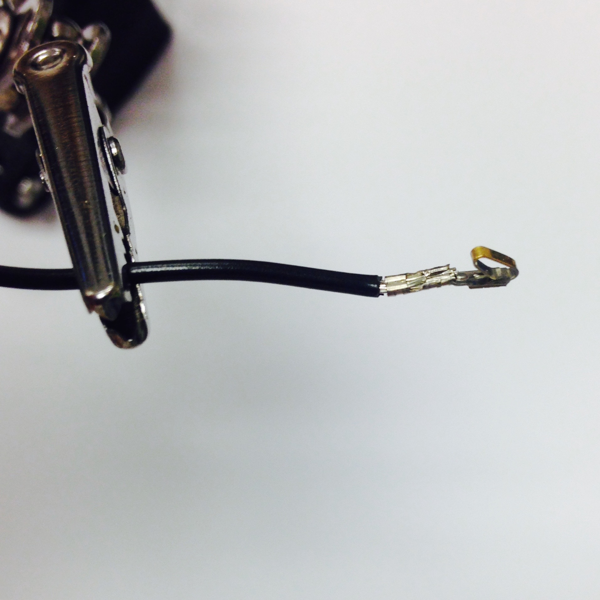
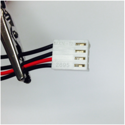
Figure 4.4: Steps for constructing LED sub-assembly.
With these four LED’s in hand (Figure 4.5(a)), insert them one by one into the Pheeno PCB. As seen in Figure 4.5(b), the white female connectors fit on the male connectors on the left side of the board. Note the location of the red wires!
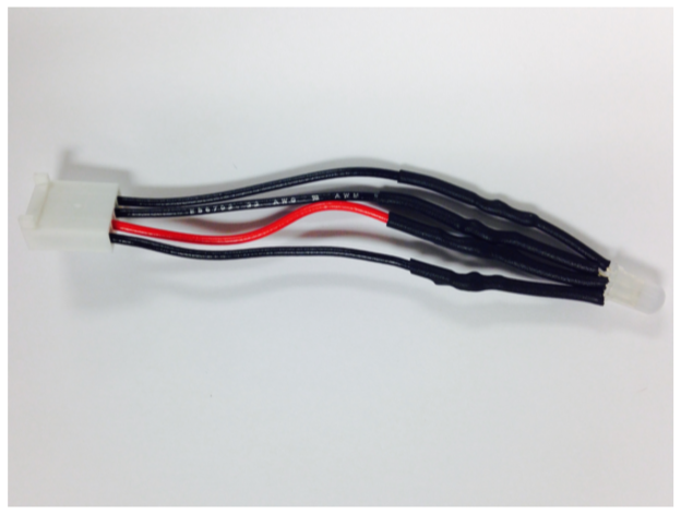
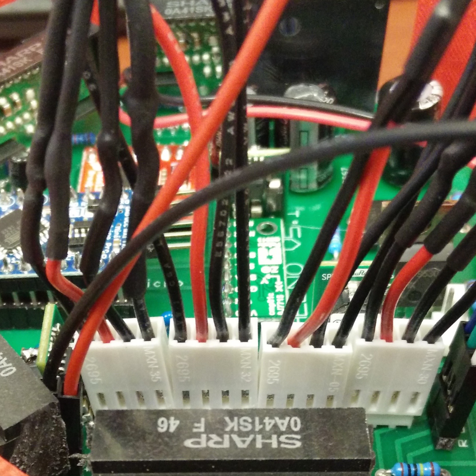
Figure 4.5: (a) Finished LED Assembly and (b) LED Connections to PCB.
Miscellaneous
The first step of Section 2, in constructing the PCB assembly, was to insert the six IR mounts. It is now time to attach the six associated infrared sensors. Figure 4.6(a) displays the location of the six sensors from an overhead view, with five oriented on the front and sides of Pheeno. It is necessary to clip the “ears” off the IR sensors to fit all of them side by side. The last sensor fits in the rear, next to the switch cable. Figure 4.6(b) shows a head-on view of Pheeno with the sensors inserted.
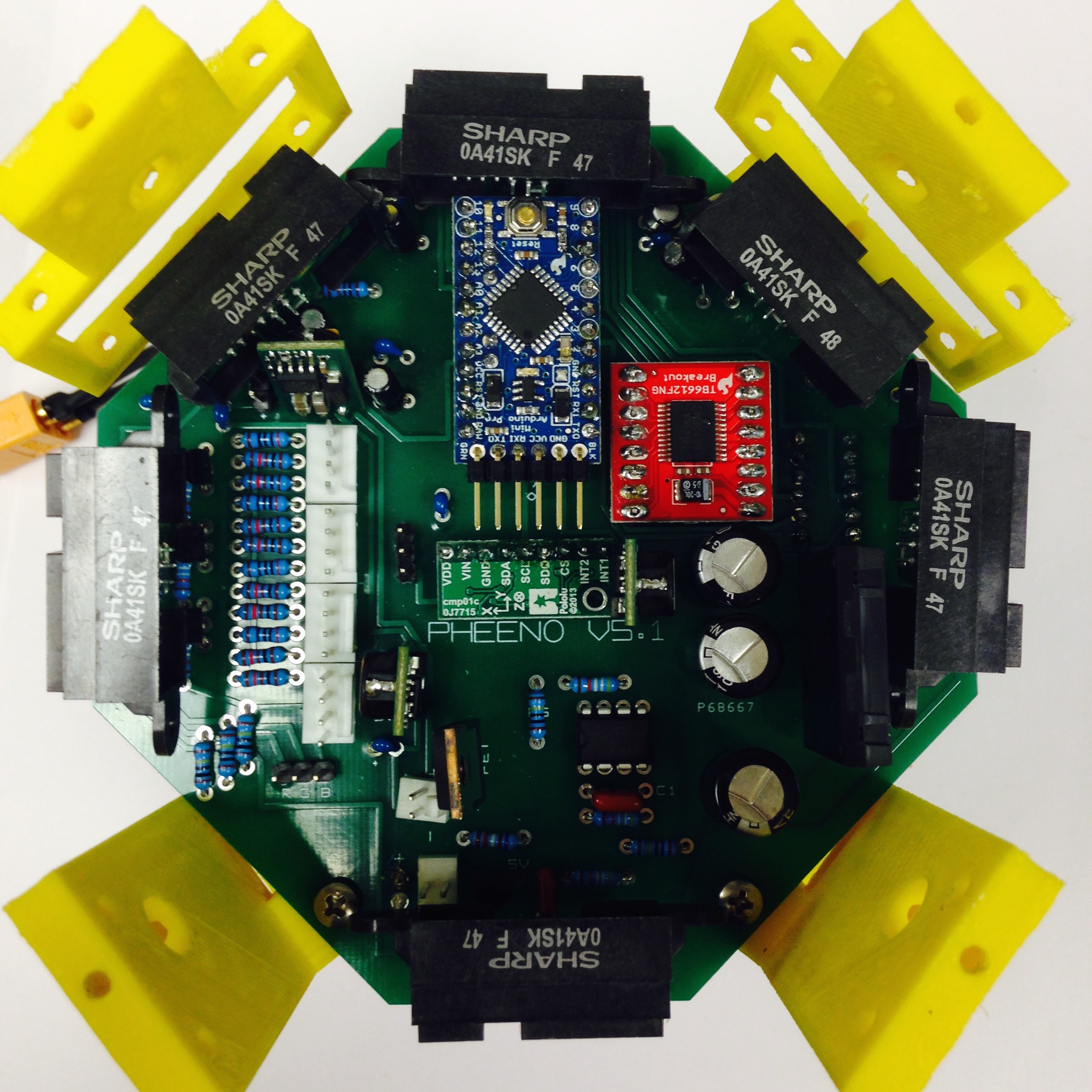
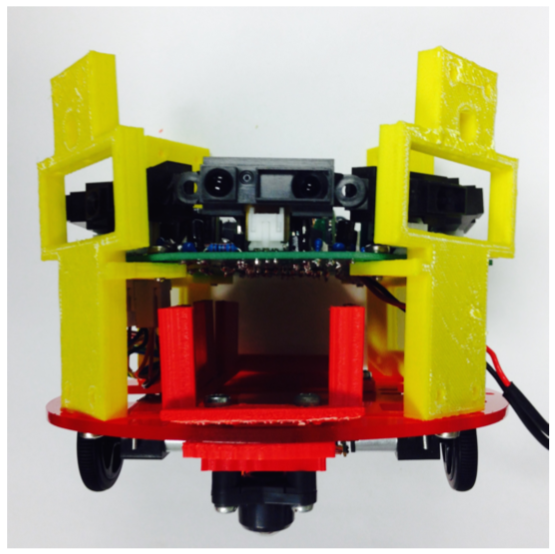
Figure 4.6: Connecting the IR sensors to the PCB.
The last step for constructing the interior of the bot is to attach the FTDI board, shown in Figure 4.7. This board is a USB-to-Serial integrated circuit and serves to allow communication between the Arduino Pro Mini and the Raspberry Pi. It also allows the Raspberry Pi or an external computer program the Arduino Pro Mini. Connect a micro-USB to USB cable to the FTDI (Figure 4.7(b)), then connect the board to the male header pins on the Arduino (Figure 4.7(c)). The orientation can be seen in Figure 4.7(d).
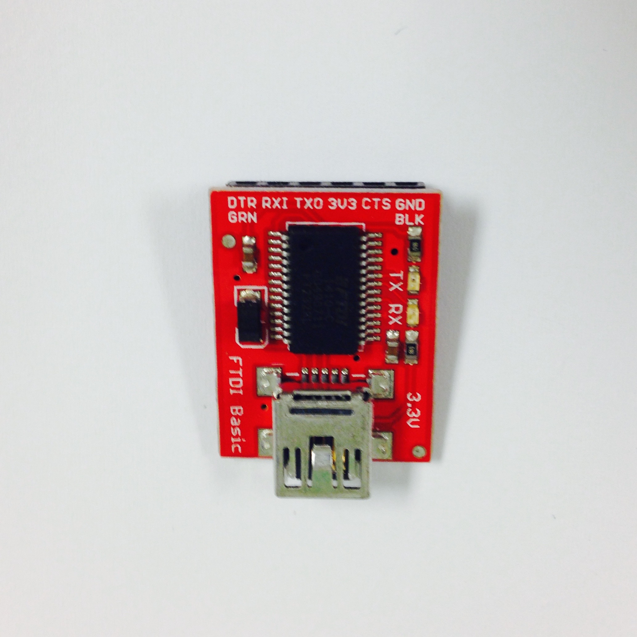
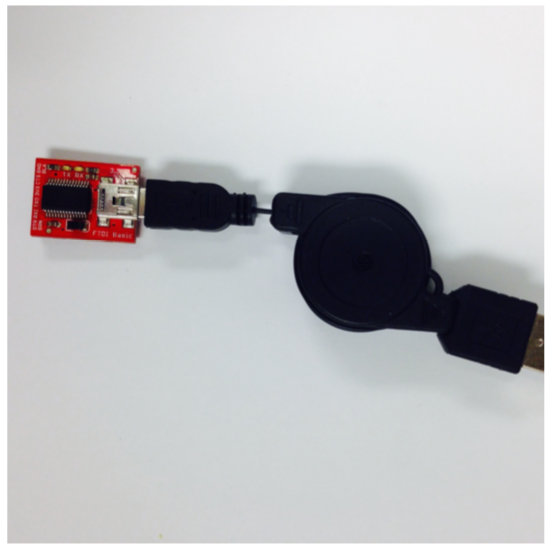
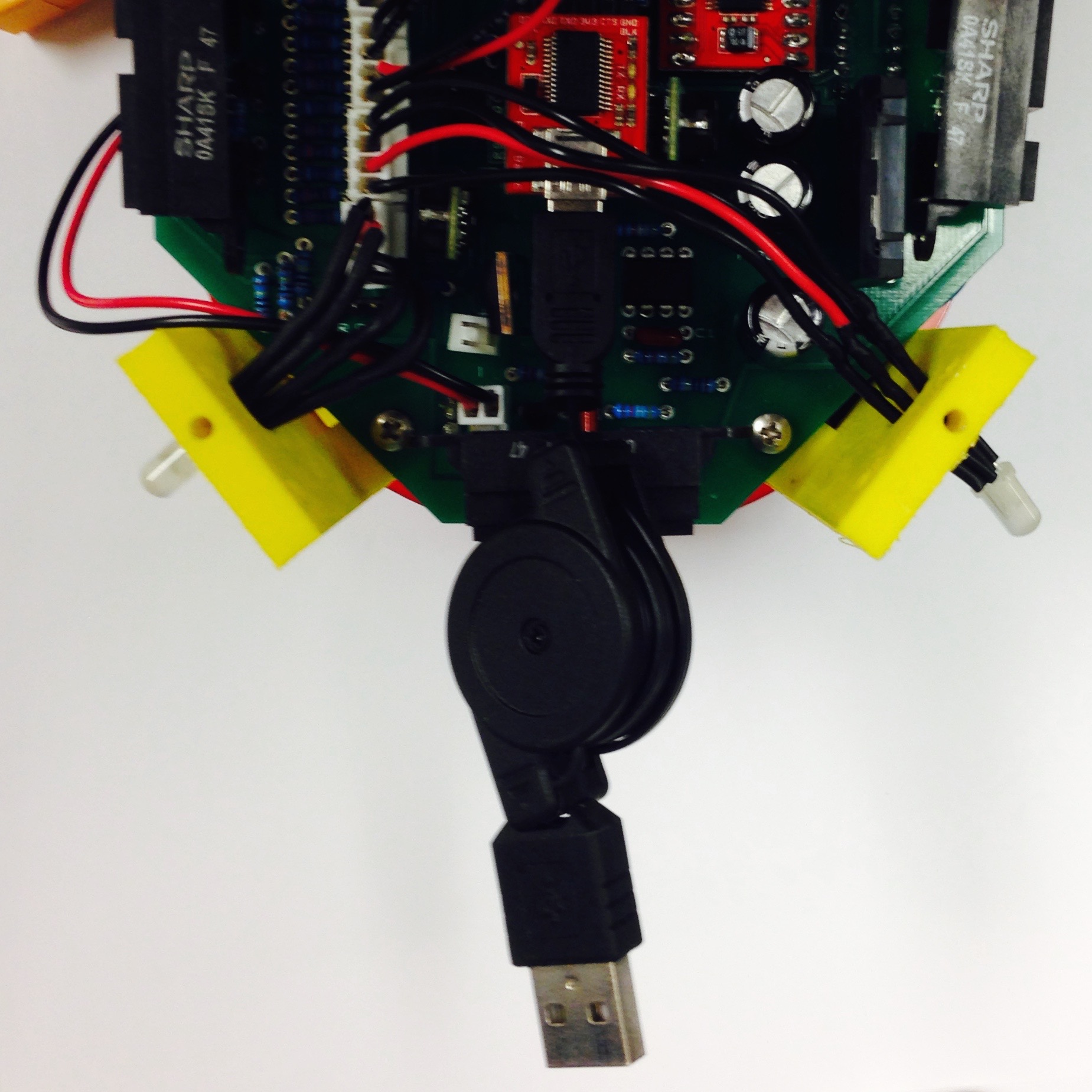
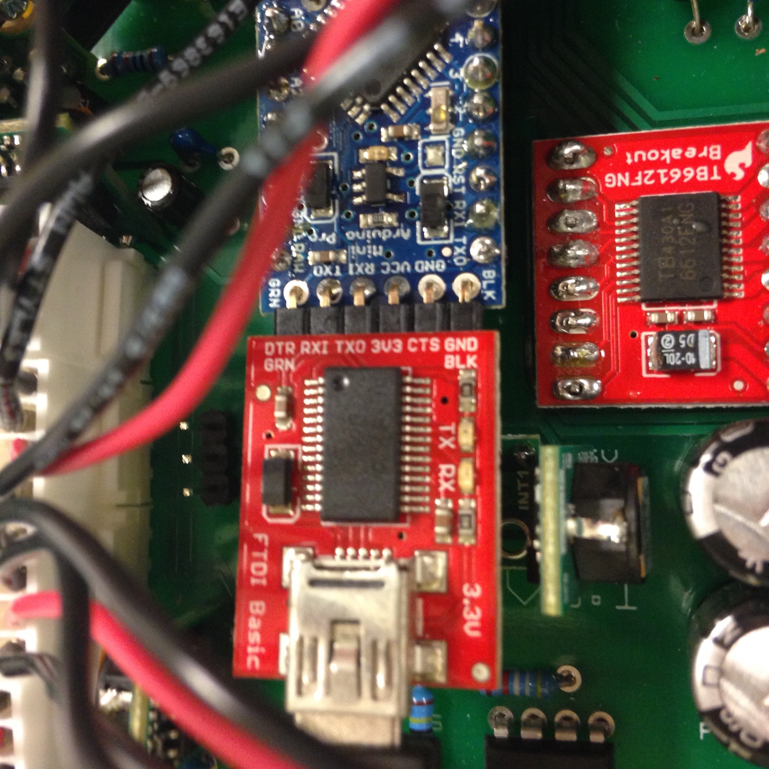
Figure 4.7: Attaching FTDI Board to Arduino Pro Mini.
Sweet, you have completed the interior of Pheeno! You are close to having a fully fabricated robot.
Robot Top
Raspberry Pi Attachment
The top of the robot is simply a Raspberry Pi attached to another laser-cut acrylic plate. Figure 5.1 displays the assembly steps. Note that this section is dedicated for assembling the hardware; chapter 6 gives the details on setting up the software on the Pi!
The Raspberry Pi is a small, linux computer developed for educational purposes. It often serves as the brains of DIY projects, and in the case of Pheeno is a practical means for doing high level computations like image processing and controller algorithms. The Pi attaches on the underside of the acrylic plate with the GPIO (General Purpose In-Out) pins aligned with the slot in the plate, as seen in Figure 5.1(c). The holes in the plate should align with the mounting holes in the Pi. Using four bolts, nuts, and 1in nylon spacers, fasten the Pi securely as seen in Figures 5.1(c) and 5.1(d).
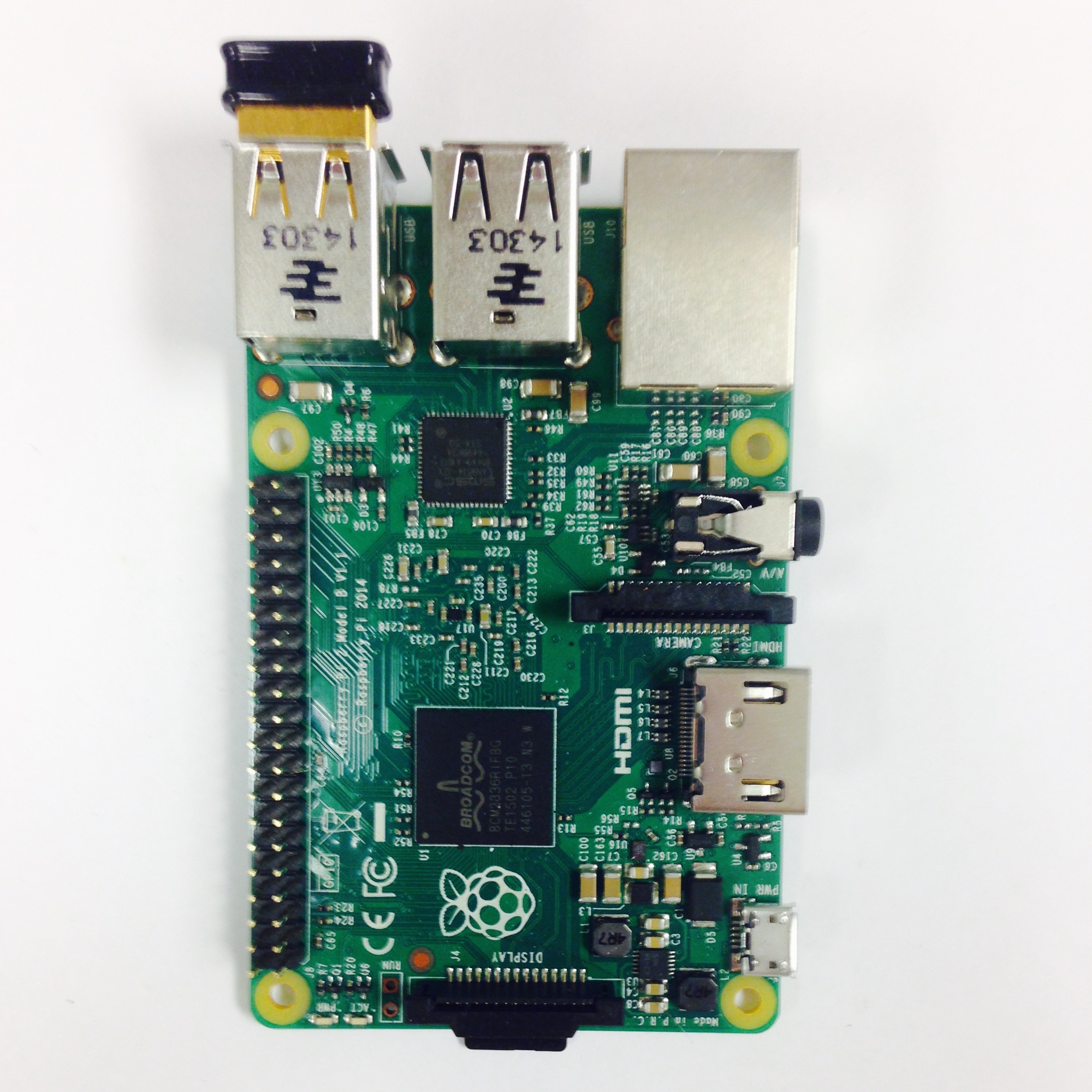
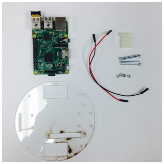
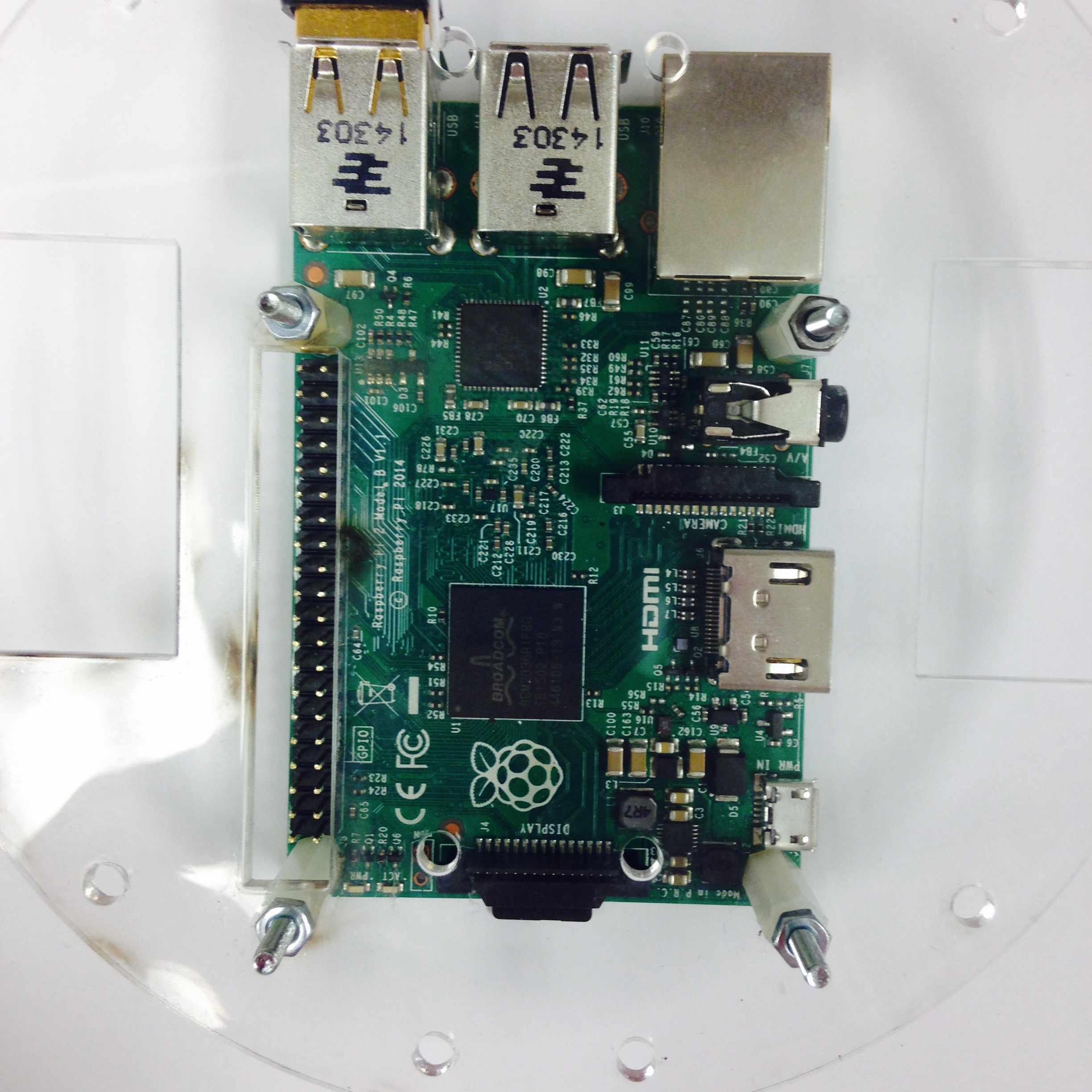
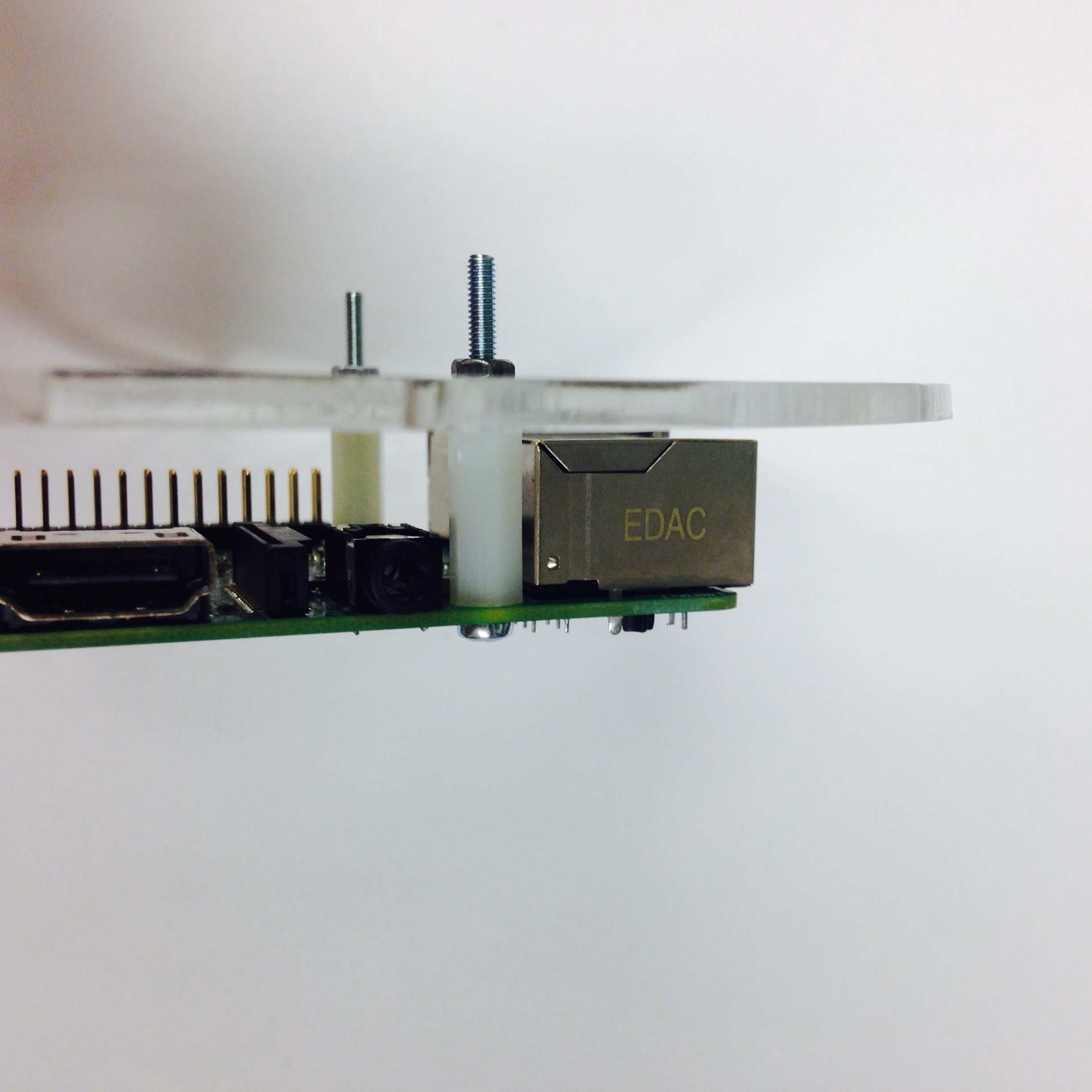
Figure 5.1: Assembly of the top of Pheeno.
Top Plate
The brains of the bot can now be put on Pheeno. Insert the USB cable from the FTDI into any of the open USB ports on the Pi, as shown in Figure 5.2(b). The slot in the top plate aligns with the slot in the base plate.
In order to power the computer, run cables from the PCB to the Pi. BE VERY CAREFUL AND PRECISE WITH THIS; A MISTAKE WILL CAUSE THE PI TO FRY! Fit a red wire with two female headers on the pin marked with a “+” on the board and a black wire on the one marked “-“. These pins are located next to the LED connection and behind the front left IR sensor. The red wire runs to the top right pin on the Pi, while the black runs to the third pin down on the right. If you are unsure with the connection to the Raspberry Pi, refer to a GPIO pin out reference. The red wire should run to a 5V power pin and the black wire to a ground pin. Reference Figures 5.2(c) and 5.2(d) for a visual guide.
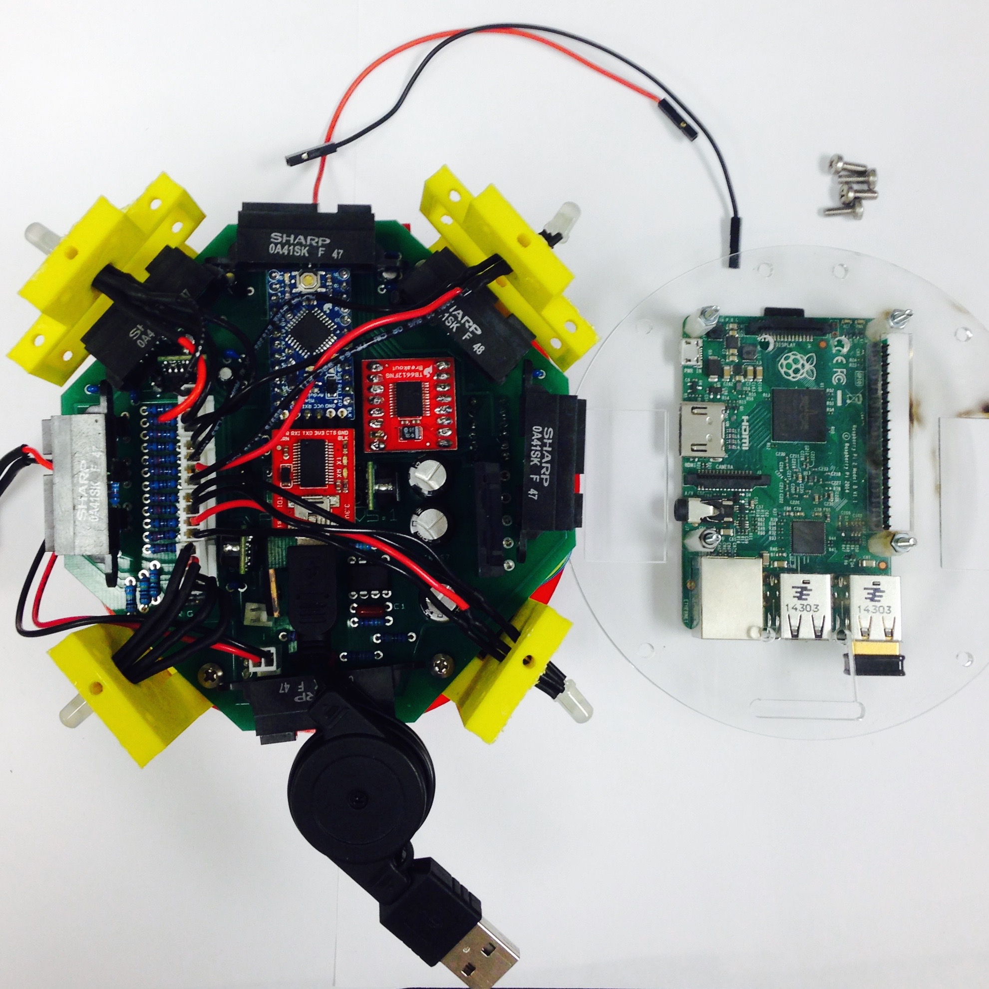
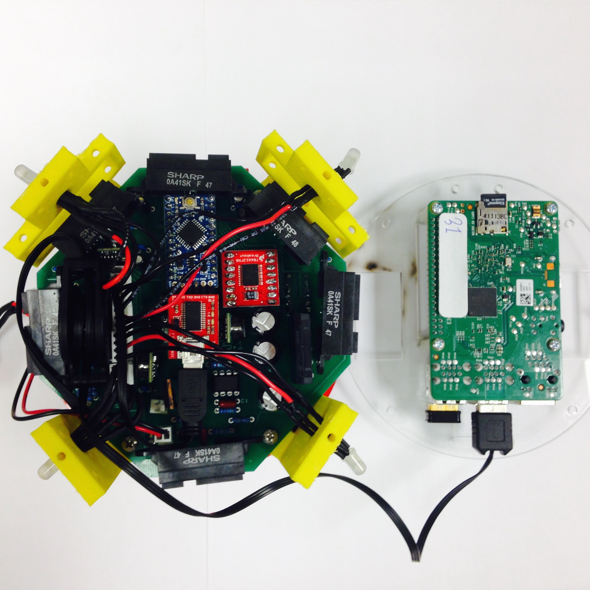
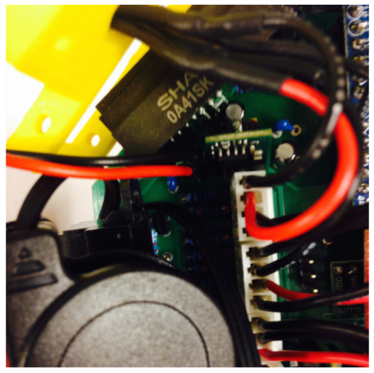
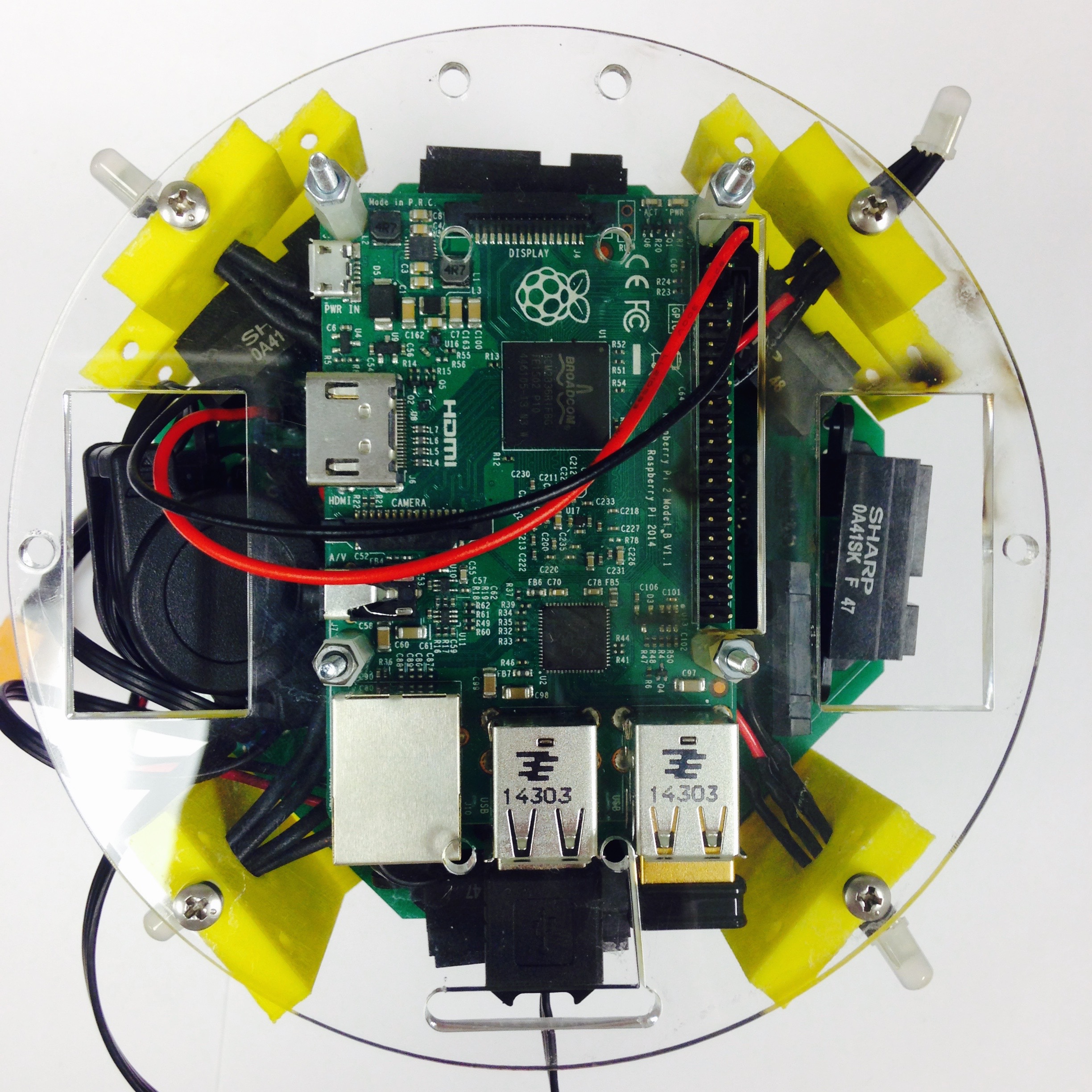
Figure 5.2: Attaching the top of Pheeno.
Finishing Touches
The last step is to attach the battery. The Pheeno uses is a 11.1V, 3S, 3000 mAh Lithium Polymer (LIPO) battery, which fits into the bracket on the lower side of the robot. Connect the XT60 connectors from the PCB jumper cable and the battery. As seen in Figure 5.3, the battery fits snugly into the slot but can easily be removed and replaced as necessary.
Hit the switch and the LEDs on the top right of the Raspberry Pi should start blinking. Congratulations, you have built a fully functioning robot! If you want to start programming Pheeno, refer to the Raspberry Pi set up guide! If you are eager to begin work on a module for Pheeno, refer to the separate module development guide. But once again, thank you for reading this guide so far and following these steps, we at ACS Lab hope you enjoy working on and with Pheeno! If you have any comments, concerns, questions do not hesitate to contact us!
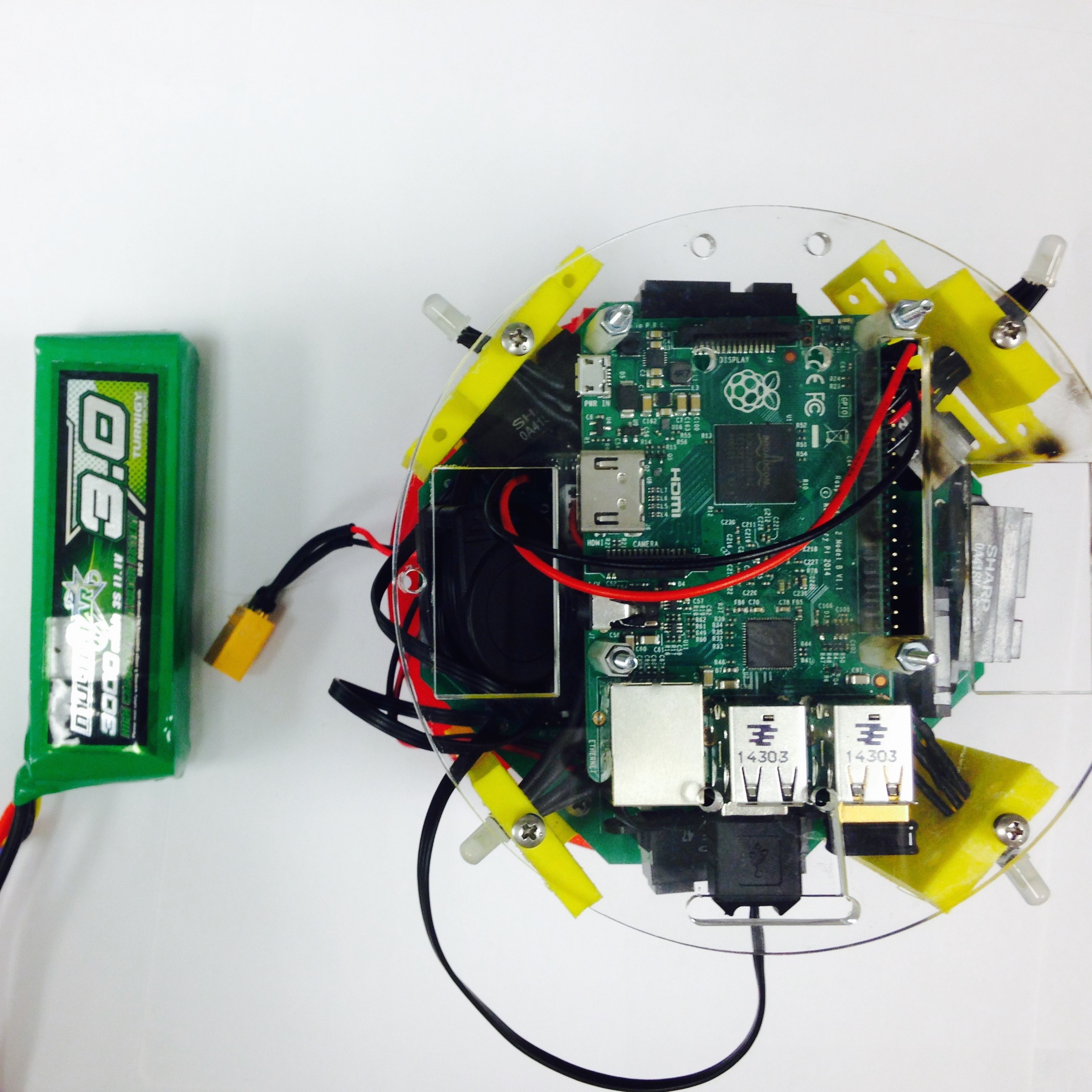
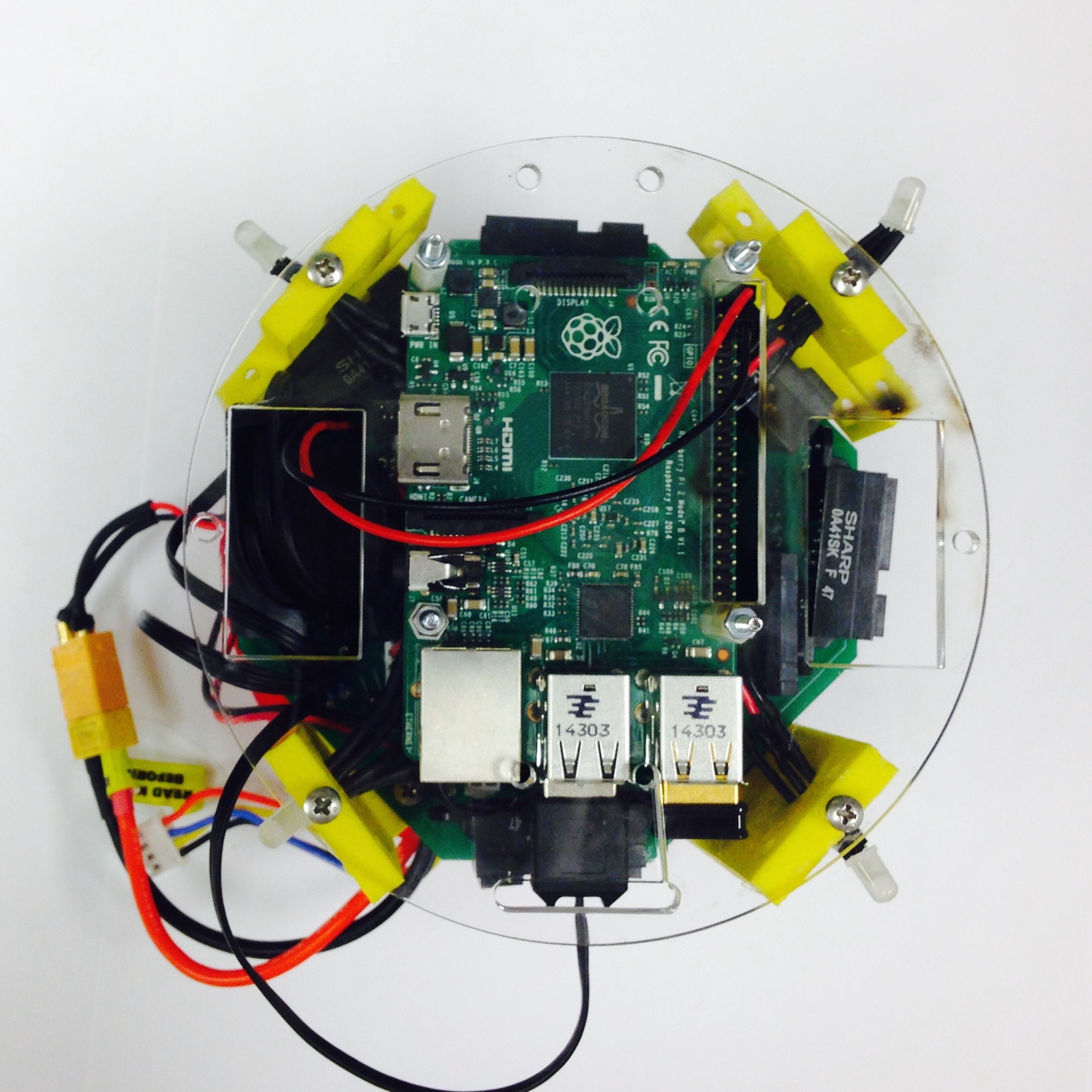
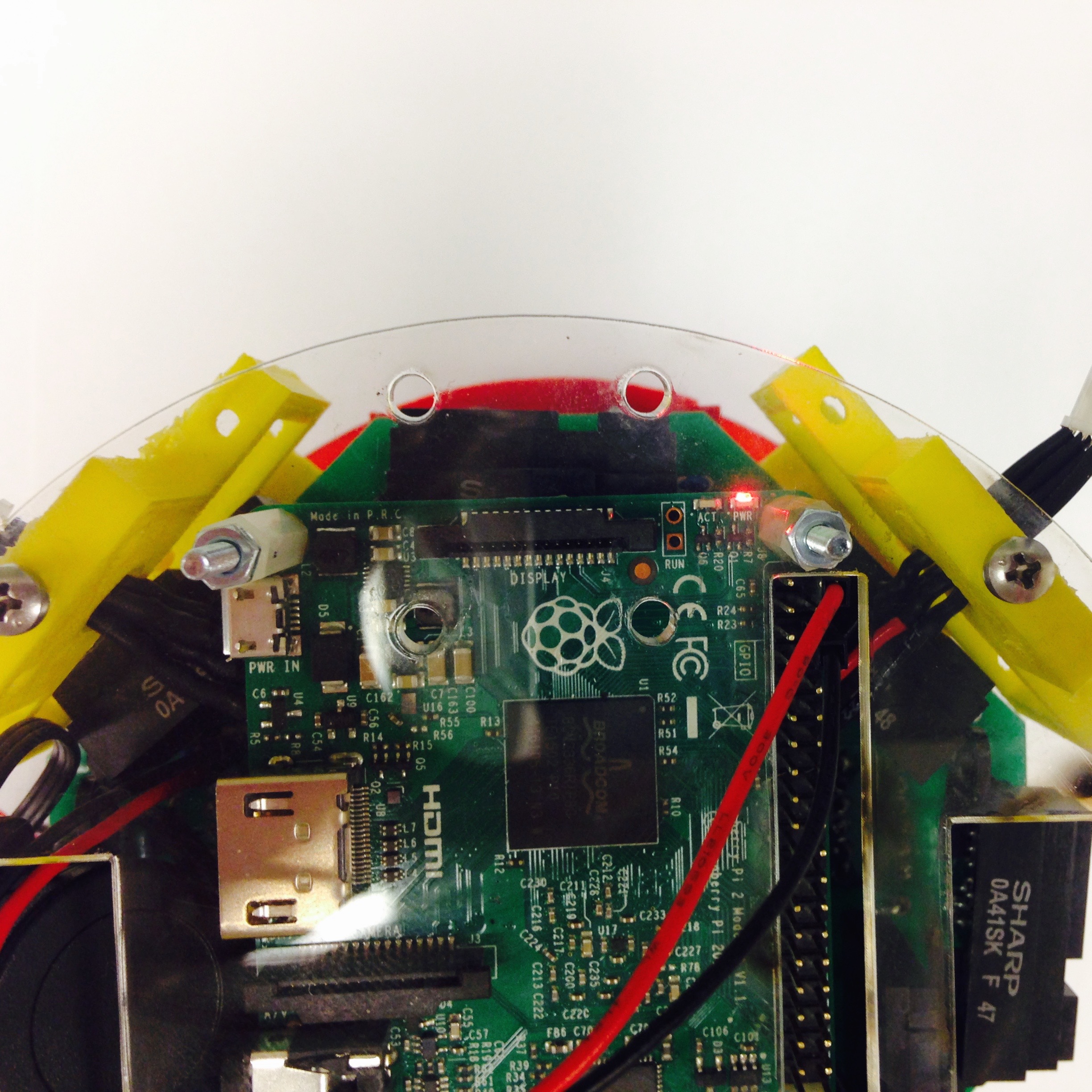
Figure 5.3: Final attachments.